Here’s a challenge. Watch this video about jack plate installation and see how many deficiencies you can find in their installation process. (My answer is at the end of this post.)
https://www.youtube.com/watch?v=CJc3LFIYRcI&t=1443s&ab_channel=BobsMachineI must admit to having fallen down a rabbit hole regarding the tightening of these bolts. I found that one of the best sources for publicly available information about bolt tightening is the National Aeronautical and Space Administration (NASA), who apparently has hired engineers that sit around all day thinking about the best way to tighten bolts. This is probably money well-spent, since NASA has had some painful experiences involving fasteners. For example, a science experiment on the space shuttle Atlantis that cost $128 million to set up was ruined by an improperly installed ¼ inch bolt (see here for the story:
https://www.nytimes.com/1992/08/29/us/tiny-bolt-blamed-in-shuttle-failure.html#:~:text=A%20tiny%20bolt%20apparently%20caused,the%20space%20agency%20said%20today. NASA sent the experiment up again on a later space shuttle, and it failed due to corrosion of a cable. I guess those NASA engineers hadn’t thought about the effects of salty Florida air.) And there is the sad story of the space shuttle flight that was delayed because a titanium nut on the hatch door handle stripped. A maintenance man called to fix it was delayed because of security problems and a dead battery on one his tools, and he had to use a hack saw to cut off the nut (story here:
https://www.newspapers.com/clip/27296929/broken-door-handle-delays-challenger/). By then, it was getting late in the day, so the flight was postponed to the next day (at a cost of about $1.2 million). Unfortunately, a cold front blew through overnight, some rubber O-rings on the rocket got too stiff, and ... you probably know the rest of the story about the Challenger flight. Much of what is discussed below came from NASA’s Fastener Design Manual, publication 1228, published in 1990 (available here:
https://mae.ufl.edu/designlab/Lab%20Assignments/Fastener%20Design%20Manual%20(NASA).pdf).
I think that part of the reason for the range of torque values recommended for outboard motor and jack plate bolts is because the bolt is part of a
fastener system comprising the bolt, nut, washers, and the objects being fastened. The force that a fastener system uses to secure two objects is obtained by stretching the bolt shaft (this force is termed the axial tension or tightening force). Bolts are elastic, but if the axial tension is excessive, the bolt loses its elasticity and becomes permanently stretched; if tightening continues, the bolt will break. It’s worthwhile to review some definitions about bolt tightening.
Ultimate tensile strength – the maximum force a fastener can maintain before fracture.
Yield strength – The axial tension at which a bolt loses its elasticity and becomes permanently stretched.
Proof load – The maximal axial tension at which the bolt maintains its elasticity. This is typically 85-90% of the yield strength.
Typical clamp load – The axial tension recommended for a fastener. This is usually about 50%-75% of the proof load. This number is generally conservative, in part because of the uncertainty of determining axial tension from a torque value. Torque wrench accuracy can be as low as +/- 25%; NASA requires that all torque wrenches be calibrated on initial use, every 30 days, or whenever the wrench is dropped on the floor!
Here is a graph that illustrates these terms:
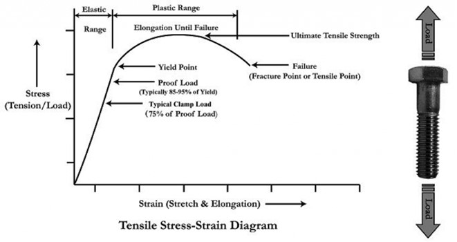
- Relationship between axial tension and strain on a bolt.
- Bolt tightening graph.jpg (32.9 KiB) Viewed 3868 times
Source: SmartBolts. Fundamentals of Basic Bolting.
http://www.smartbolts.com/fundamentals/#:~:text=Proof%20load%20is%20defined%20as,95%25%20of%20the%20yield%20strength.
Unfortunately, the axial tension on a bolt cannot be easily measured, so we are left with determining the force required to turn a nut on the bolt. This is the torque value, and only about 10% of the torque is due to the axial tension on the bolt; the rest is due to friction in the fastener system. The axial tension can be estimated from the bolt torque using some standard engineering formulas you can review here:
https://www.engineeringtoolbox.com/bolt-torque-load-calculator-d_2065.htmlA given torque on a bolt will yield different axial tensions depending on the bolt material, the thread design, the design of the nut and washer, whether the bolt threads are lubricated, and even whether it is the bolt head or the nut is being turned. Bolt torque charts usually list values for dry bolts with the nut being turned, but some charts include alternate (and often much lower) recommended torques for lubricated bolts. Basically, if you lubricate a bolt before tightening it but you use the same torque specified for a dry bolt, you risk damaging the fastener.
Here are a few other things I learned from reviewing the NASA manual:
- Most locknuts (including Nyloc nuts) don’t really help maintain bolt tension; they are loss retention devices that keep the nut from falling off the bolt.
- Split ring lock washers are essentially worthless for maintaining bolt tension. (Yes, I was surprised, too. Watch this video:
https://www.boltscience.com/pages/helicalspringwashers.htm)
- For multiple fasteners, the bolts should be tightened sequentially in a crisscross pattern.
- There should be two threads protruding past the end of the nut.
- Bolts should be re-torqued after installation to account for relaxation of the fastener system.
- NASA recommends against using jam nuts because it is difficult to obtain reliable torque values for the fasteners. They do lock the nuts in place effectively, though, which is probably why Yamaha recommends them.
The charts I pulled up online indicated that the appropriate torque for the bolts I had received from Bob’s Machine was about 55 ft-lbs (with dry threads), but I wasn’t quite ready to give up on finding out why Mercury had such a high torque (90 ft-lbs) when this type of bolt was used to mount the engine to a jack plate. I found a Mercury online customer service information site that lets you send them a message if you enter your Mercury outboard serial number, so I sent them this:
Sent to Mercury Marine online on 1/31/2023 (
https://www.mercurymarine.com/en/us/contact/outboard-customer-assistance)
I am installing an Atlas Micro Jacker hydraulic jack plate on my 1991 Mercury 90 HP outboard engine. My OEM service manual (circa 1989) does not specify bolt torques for this installation, but the latest version of the Mercury Operation, Maintenance, and Installation Manual I could review online (2016 version) gives recommended torques of 55 ft-lbs for the transom bolts and 90 ft-lbs for the bolts attaching the engine to the jack plate, using “validated fasteners provided by Mercury”. My local Mercury dealers use ½”-20 F593C bolts (304 stainless steel bolts with brass lock nuts) supplied by THE for this type of installation, and they do not bother to use a torque wrench. Typical torque specifications for this bolt are in the range of 40-55 ft-lbs, and my calculations (using a yield strength of 65,000 psi and stress area of 0.1599 sq.in.) indicate that a torque of 90 ft-lbs will exceed the load at yield strength of this bolt. (load at yield strength=yield strength x bolt stress area = 65,000 psi x 0.1599 sq.in.=10,393.5 lbs. Torque at yield strength load: T=KdF, 0.2 x 0.5in. x 10,393.5 lbs./12 = 86.6 ft lbs. My question is: Is your torque specification for jack plate attachment (90 ft-lbs) for a different type of bolt, or is this an error on your part, or on mine?I got this reply a week later (the typos are theirs):
We are very sorry, as there is not documentation on what the tourque specs should be while using a jack plate. We have looked in installation manuals, as well as service manuals. Mercruy Marien can only suggest at this point you work with the manufacture that made the jake plate you are using to see if they have any instite on what tourque value will work for your application.
We hope this information is helpful to you. Should you have any further questions or concerns, please contact our Customer Service department at 920-929-5040 between the hours of 7:30 am and 4:30 pm, Monday through Friday, CST.
Sincerely,
Mercury Outboard Customer Assistance
Ref: 2023-00011638Finally, I sent another message to Bob’s Machine saying that neither my boat manufacturer nor my engine manufacturer would supply torque values for this installation. I immediately got a reply: 55 ft-lbs. And that was the number I used.
Finally, there is the question of what kind of sealant to use. Personally, I think 3M 5200 is a poor choice for this installation. What if the unit breaks, or performance deteriorates and I want to remove the jack plate? I can’t see the logic of using an adhesive that will damage on removal the objects you are bonding unless you are confident that you will
never have to remove the equipment. I went with Loctite PL Marine Fast Cure Adhesive Sealant, which is equivalent to 3M Marine Adhesive Sealant 4000 UV and is available at my local Lowe’s. I applied the Loctite on the plate as well as around the bolt holes to minimize any vibration between the transom and jack plate, which will reduce the chance of fasteners loosening over time. Here is a photo of the final installation.
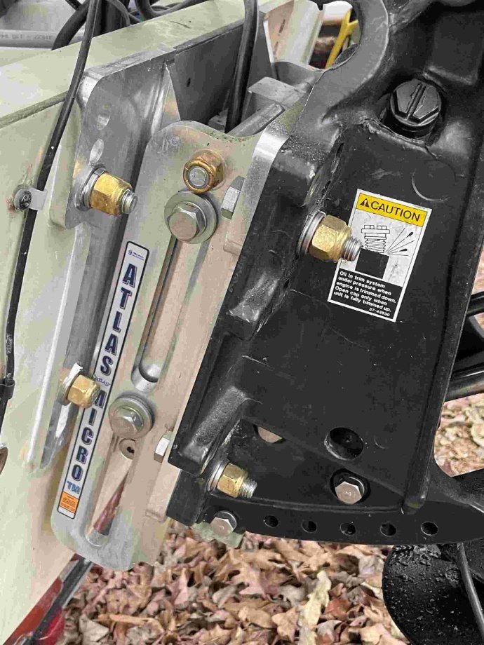
- Final installation of jack plate on my Montauk 17
- jackPlateInstall.jpg (148.91 KiB) Viewed 3155 times
My 3½ inch bolts turned out to be a little short, but the threads do engage the nylon ring of the locknut, so I’m going to leave them as is for now. Torquing to 55 ft-lbs seemed quite snug, but there was no cracking of the fiberglass on the transom. I couldn’t get the socket of my torque wrench around the nut on the lower transom bolts, so I was forced to torque those fasteners by turning the bolt heads.
Next step: Testing the unit on the water.
Bob’s Machine video deficiencies:
- Using a sealant that will pull off the gelcoat if the jack plate is ever removed (although this sealant is commonly used for mounting jack plates).
- Sealant is on bolt threads, not wiped off before nut installed.
- Nuts used do not appear to be self-locking.
- Impact wrench used to tighten nuts.
- No torque wrench used (and this deficiency is acknowledged in the video).
- Fasteners are not cross tightened.
- No follow-up re-torquing after installation
