Modifying the antenna relay circuit to permit operation with solid-state transceivers
The Heathkit SB-220 is one of the most popular amplifiers ever sold. It was designed in an era when most amateur equipment was based on vacuum-tube technology. Because of this, special care is needed if the SB-220 is to be used with solid-state transceivers.
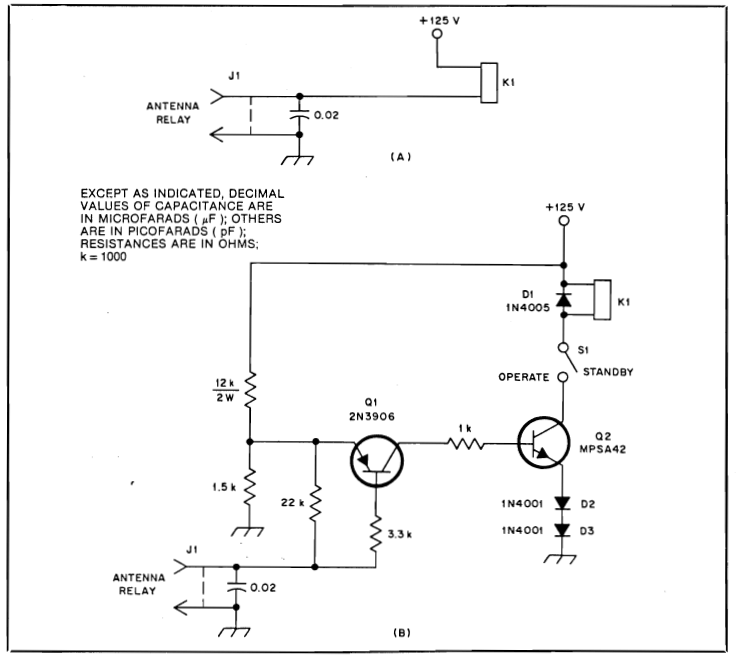
The SB-220 goes into transmit mode when the hot contact at its rear-panel ANT RLY jack (J1 in Fig. 1A) is shorted to ground, actuating K1, the SB-220 antenna relay. The open-circuit DC voltage at this jack is 125-Volts; the short-circuit current is 25-milliAmperes. Vacuum-tube-based exciters usually have no trouble switching power at this level. Solid-state rigs are a different story.
My ICOM IC-740 transceiver can't switch 125-Volts at 25-milliAmperes because the maximum ratings for its amplifier-control relay are 24-Volts and 1-Ampere DC. Other solid-state transceivers likely use relays or open collector transistors of similar ratings for amplifier control. The switching problem is complicated by the fact that the SB-220 antenna-relay solenoid is not shunted by a spike-suppression diode. The transient voltage developed by the solenoid's collapsing magnetic field can exceed the supply voltage. (If you've ever gotten a poke from a relay solenoid back EMF, you know this voltage is not just theoretical!) With the 24-Volt rating of the IC-740's control contacts in mind, a direct amplifier-control connection between the SB-220 and the IC-740 seemed to invite trouble.
Figure 1B shows my solution to this problem. With Q1 and Q2 handling the actuation of K1, voltage at J1 is reduced to approximately 12-Volts. Short circuit current through J1 is about 2-milliAmpere. Because the SB-220 must be opened to make this modification, now is a good time to install an OPERATE/STANDBY switch, S1, to save switching the SB-220's tube filaments on and off.
There is plenty of room under the SB-220 chassis for mounting the switching components; the entire circuit can be assembled on a tie strip and mounted to an available under-chassis screw. I installed my version of the Figure 1B circuit next to the SB-220's 125-VDC supply, just behind the SSB/CW rocker switch. (Take proper high-voltage safety precautions when you make this modification. Lethal voltages exist in the SB-220.) Dress the wiring for minimal coupling to the RF circuits under the chassis and near the antenna relay. As installed in my SB-220, this circuit shows no susceptibility to RFI.
The page has been accessed times.
Copyright © 1988, 2014 by James W. Hebert. Unauthorized reproduction prohibited!
This is a verified HTML 4.01 document served to you from continuousWave
URI: http://continuouswave.com
Last modified:
Author: James W. Hebert
This article first appeared in QST Magazine for January 1988, page 45.
The schematic drawing was made by the American Radio Relay League from the author's design.
