continuousWave --> Whaler --> Reference
Permanent Magnet Alternators
by James W. Hebert
The first permanent magnet generator which produced alternating current ("alternator") was demonstrated by French instrument maker Hippolyte Pixii in 1832. Unfortunately, at that time direct current was much more useful and perhaps the invention did not gain the notoriety it might have otherwise deserved. In 2006, some 174 years later, the permanent magnet alternator is still the most efficient way to generate an alternating current, and, with the subsequent invention of the solid-state power rectifier, a very effective way to produce direct current as well.
Most outboard engines include a permanent magnet alternator for generating electrical power for operating the engine and for re-charging a battery which is associated with the engine. This article examines in detail the permanent magnet alternator components and circuitry commonly used in outboard motors.
Electromagnetic Induction
The permanent magnet alternator in an outboard motor uses the principal of electromagnetic induction to convert surplus energy of motion from the motor into electrical energy. If an electrical conductor such as a copper wire is moved relative to a magnetic field flux, or, if conversely a magnetic field flux is moved relative to a stationary wire, the magnetic field flux will induce an electromotive force (EMF) or voltage into the wire. The strength of the EMF or its voltage will be proportional to the rate of change of the flux of the magnetic field. If the wire is wound into a coil, the EMF will in proportion to the number of turns of the coil.
If the conductor is connected to electrical loads, current will flow, thus generating electrical power. The greater the electrical load placed on the generator, the greater the mechanical load placed on the engine creating the energy of motion turning the generator.
An electrical generator using this principal therefore requires:
- a source of energy of motion for rotation
- a source of magnetic field
- a conductor in motion relative to the magnetic field
Permanent Magnets
The magnetism of a permanent magnet creates the magnetic field. Typically more than one magnet is used. The magnets are set in motion relative to a fixed coil by direct drive from the crankshaft of the motor, creating the relative motion between the two. Because the coil of wire is stationary, there are no complex moving electrical connections required. The permanent-magnet alternator has advantages over other techniques:
- inherent reliability because of its brush-less design;
- fewer moving parts
- requires no exciting voltage or current
- no parts which rub or wear (like rubber drive belts, tensioner pulleys, or electrical brushes) thus extremely long mechanical life span
A permanent-magnet alternator will generally be more efficient than other electromagnetic induction generating devices. However, it does have a disadvantage. Due to the fixed strength of the magnetic field generated by the permanent magnets, and the fixed number of turns in its coils, the voltage output of a permanent magnet alternator will vary with the rate of change of the magnetic flux. The rate of change of the flux is directly proportional to the rotational speed. Therefore either varying the speed of rotation or some type of external electrical control is necessary to maintain the output voltage at a regulated level.
Common Implementation
A very common implementation of the permanent magnet alternator in outboard engines is incorporation of permanent magnets into the flywheel of the engine. The magnets are located radially in suitable pockets in the steel flywheel. This conveys several advantages:
- the steel of the flywheel can be used to enhance the magnetic field and increase coil current;
- magnetic attraction to the steel tends to keep the magnets in position;
- centrifugal rotational energy will tend to keep the magnets in position;
- the weight of the magnets can be useful as part of the flywheel weight. The flywheel stores mechanical energy for the motor, enhancing its operation, too.
The stationary coil or stator is typically located under and inside the rotating magnets. The coil will be protected by the cover of the flywheel. In an outboard engine this generally results in the coil being mounted atop the engine. This has a drawback of placing the coil in an area of higher temperature.
To improve the efficiency of the permanent magnet alternator, it is common to employ multiple magnets and multiple coils wired in series. The magnets are arranged radially around the flywheel. The stationary coil or "stator" is typically wound into multiple segments with matching radial spacing, or, in some cases and as seen below, at a spacing which is a multiple of the magnet spacing. In some cases the windings of the coil segments are reversed in alternation, i.e., one coil is wound clockwise and the next is wound counter-clockwise. This creates an alternating flow of current. The coil are also typically wound around iron or steel pole pieces, to enhance the coupling of magnetic flux from the rotating magnets into the coil windings.
An outboard motor needs electrical energy for its ignition, and this is typically generated in the same way, however the term magneto-ignition is often used in place of permanent magnet alternator. The coils associated with the magneto-ignition are also located under the flywheel. In some cases these coils are interspersed with the stator coils of the permanent magnet alternator.
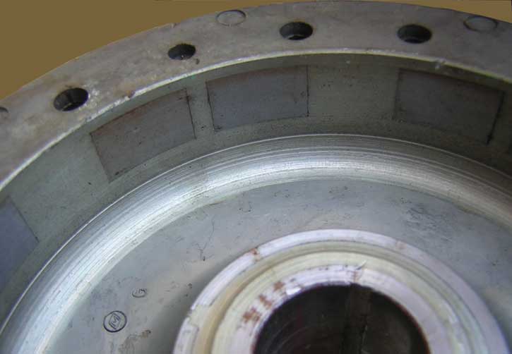 |
Flywheel Permanent Magnets
Set into the steel flywheel are permanent magnets. Shown here are a total of 12 magnets, but they are arranged in pairs and spaced at 60-degree intervals. Because of the alternating wiring of the coils associated with these magnets, we can deduce that each pair of magnets is of alike orientation, and the N-S orientation is the same from pair to pair, i.e., either all-N or all-S orientation.
Photo Credit: James W. Hebert |
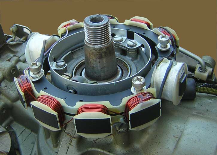 |
Stator Coil Windings
The flywheel has been removed from the top of this engine to reveal the ten coils located beneath it. The coils are spaced at 30-degree intervals, which implies 12 coils, but two positions do not have coils. Eight of the coils are wired in series and form the stator coil for the alternator's main output used for battery charging. Note that the winding of the series coils alternates between clockwise and counter-clockwise. The two other coils are associated with the magneto-ignition. The voltage these two coils generate is used to created the high-voltage for the spark ignition.
Photo Credit: James W. Hebert |
The rotation of the flywheel magnets and the wiring of the coils are somewhat awkward to draw in their circular configuration. If we unwind the circle into a straight line, the arrangement of magnets and coils can be
represented like this:
M = magnet
a = coil wound clockwise
b = coil wound counter-clockwise
i = ignition coil


At 0-degree of rotation:

i__a__b__a__b_____i__a__b__a__b_____
M     M     M     M     M     M

At 30-degrees of rotation:

i__a__b__a__b_____i__a__b__a__b_____
   M     M     M     M     M     M

At 60-degree of rotation:

i__a__b__a__b_____i__a__b__a__b_____
M     M     M     M     M     M

At 90-degrees of rotation:

i__a__b__a__b_____i__a__b__a__b_____
   M     M     M     M     M     M

and so on.
Inspecting the pattern we see that the voltage generated in all the "a" and "b" coils is additive, that is, all the magnets align with a coil of the same winding polarity. At 0, 60, 120, 180, 240, and 300-degrees of rotation, all of the M magnets are aligned with "a" coils (clockwise winding), producing current flow in the coil in one direction. And at 30, 90, 150, 210, 270, and 330-degrees of rotation, all of the M magnets are aligned with "b" coils (counter-clockwise winding), producing current flow in the opposite direction. Thus each revolution of the flywheel and magnets produces six cycles of alternating current in the stator coil. Also we see that the ignition coils, "i", produce a pulse every 60-degrees of rotation, or six pulses per revolution. This current is used to power the ignition system.
Alternating Current Output
The effect of the rotating magnets and the stator coils is to create an alternating current whose frequency is proportional to the rate of rotation and the number of magnet poles in the flywheel. Because the frequency of the alternating current produced is proportional to the rotational speed of the engine, this voltage is also sampled and applied to a frequency measuring gauge which has been calibrated in revolutions per minute. This becomes the engine's tachometer. In the engine pictured above, each revolution produces 6-cycles of output. At a rotational speed of 600-RPM, the alternator produces an output at a frequency of
 600-REVOLUTION       1-MINUTE         6-CYLES
________________ X  ___________   X  ____________  =  60 CYCLES/SECOND
    MINUTE           60-SECOND        REVOLUTION
Rectifier
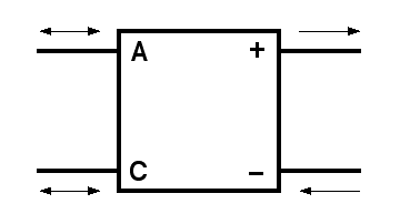 |
Full Wave Bridge Rectifier
The full wave bridge rectifier accepts alternating current at its inputs, A and C, and produces direct current at its outputs, (+) and (-). It contains four solid state diodes.
Drawing Credit: James W. Hebert |
To transform the alternating current into a direct current, the output is applied to a rectifier. The typical configuration is to use a solid-state full-wave bridge rectifier. We can describe a full-wave bridge rectifier as a four terminal device. The input terminals, A and C, permit input current to flow between them in either direction. The output terminals, (+) and (-) permit current to flow only from (+) to (-). The effect of a full-wave bridge rectifier is to convert an alternating current into a direct current. The stator coil is connected to the A and C input terminals of the full-wave bridge rectifier. The negative (-) output of the rectifier is connected to the engine block or battery negative. The positive output (+) of the rectifier is a pulsating direct current which is connected to the battery positive. Whenever the output of the rectifier exceeds the battery voltage, current will flow from the rectifier into the battery, causing the battery to be re-charged.
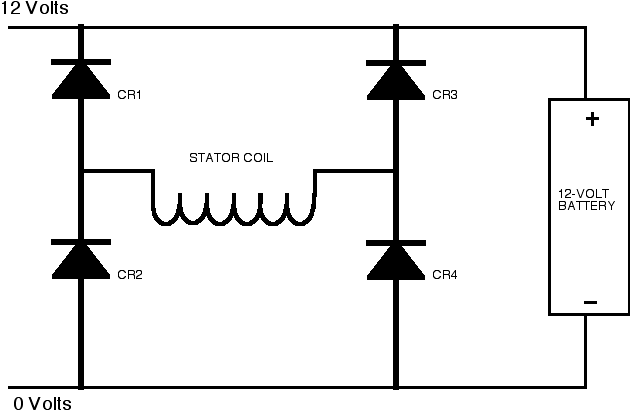 |
Charging Circuit
A typical outboard motor charging circuit. The components have been re-arranged to better show their electical operation. Click on the drawing to see an animation showing how the diode conduction changes with changing current flow in the stator coil.
Drawing Credit: James W. Hebert |
The stator coil and magnet arrangement shown above delivers 6-cyles of alternating current to the rectifier for each flywheel rotation. The rectifier converts this into a pulsating direct current having 12-pulses per rotation of the flywheel.
In a solid-state silicon rectifier, there is a voltage drop of about 0.6 volts across each rectifier. As current flows through the rectifier, this voltage drop causes a power loss which is dissipated as heat. In a rectifier which has to carry 50-amperes of current, this implies about 50 x 2 x 0.6 = 60-watts of heat. The rectifier is typically constructed with a physical assembly which is designed to absorb this heat, called a heat sink. In larger engines, the rectifier assembly and its heat sink are often cooled by water from the engine cooling system.
It is almost universal in outboard motors that the rectifier is not located under the flywheel with the stator coil. This permits the rectifier to be located for better repair or replacement, and also to have access to cooling water flow for removal of excess heat.
Voltage Regulation
The rectified output voltage from a permanent magnet alternator will vary in proportion to the engine speed. In general, the stator coil is wound so that at idle speeds the voltage output will be just greater than the battery voltage. This provides battery charging current even at idle. As the engine speed increases, the voltage output rises, creating more current available for battery charging. As the engine speed increases further, the voltage output rises above the level useful for battery charging, and some form of voltage regulation has to be applied to limit the voltage so as not to harm the battery.
To adjust the voltage output from the permanent-magnet alternator, the only variables available are engine speed or number of turns of wire in the coils. In a device whose sole purpose is to generate electrical power, the speed of the engine driving the alternator can be governed is such a way as to stabilize the output voltage at the desired level. But, in a marine outboard engine application, the engine speed must be set to suit the vessel and not the electrical generating system, and adjustment of the engine speed is not an option for voltage regulation. Some other type of voltage regulation must be used.
In the simplest (and most common) implementations of a permanent-magnet alternator, there is only a single coil winding, and the number of turns of wire in the coil cannot be varied. Thus, the number of coil windings cannot be easily varied to adjust the output voltage. This leaves only an external electrical voltage regulator as a method to control the output voltage. The most common approach is to include a regulator which operates by diverting excess voltage into another load. Such a regulator requires that the unregulated voltage always be greater than the desired regulated voltage. The regulator drops the output voltage to the desired level by inserting a variable loss element into the current path. Excess voltage is dissapaited across this variable load, resulting in a stable output voltage. The power dissapaited in the regulator load generates heat. This additional heat must be dissipated in order to prevent a heat build up at the regulator.
To a certain extent the electronic regulator works well because the voltage output of the alternator tends to drop as the output current increases. At low current outputs, the unregulated voltage will be high, and there will be a large drop in voltage across the regulator. However, because the current is small, the power lost in the regulator will not be excessive. As more current is drawn from the alternator, the unregulated voltage tends to drop. This makes the voltage drop across the regulator smaller, and this mitigates the power lost. Even though the current through the regulator is higher, the power lost in the regulator tends to be less than expected due to the natural drop of the unregulated voltage. Thus at higher current flows, but with a lower voltage drop across the regulator, the amount of heat to be dissipated is not as high as one might expect. In some cases the regulators actually run cooler with higher current loads due to the decrease in voltage drop across the regulator.
Because of the almost unlimited cooling capacity available in an outboard motor from the raw water cooling system, it is common in larger capacity alternators to use a water cooled heat sink to dispense with the waste heat from the regulator. In some engines, this heat sink is incorporated in the engine cooling system and can help the engine warm up faster when initially run. In small capacity alternators, an air-cooled heat sink is sufficient.
More modern implementation of the permanent-magnet alternator use multiple coil windings which are kept separate to permit them to be combined in series or parallel, according to the engine speed. The coils can be reconnected electronically to be in either a series connection or a parallel connection. The coils are connected in series at low speeds in order to provide useful voltage output at low rotational speeds. When the engine speed increases, the coils are switched to a parallel arrangement to produce more current. The Evinrude E-TEC engine uses this advanced technique to enhance the efficiency of the alternator.
Modern voltage regulating techniques can also use a pulse width modulated regulator which controls the flow of current in such a way to reduce and regulate the voltage without having to waste so much energy creating heat. The output current is rapidly switched on and off many times per second so that the average output voltage is regulated to the nominal level desired. Current is either switched completely on or switched completely off. Thus there is little voltage drop across the regulator and not much wasted energy creating heat. The battery in the circuit acts as a storage device, smoothing out the flow of this very pulsating direct current. The Evinrude E-TEC uses this more advanced form of voltage regulation. By using more sophisticated voltage regulating techniques, the overall efficiency of the permanent magnet alternator is improved.
Tachometer Signal
A signal for driving a tachometer is often taken from the permanent magnet alternator. Typically the signal is taken from the stator coil output as it is applied to the rectifier. The attachment of the battery and the rectifier to the circuit affects the ouput of the stator coil somewhat. The positive voltage peak is limited to about a volt above the positive battery voltage, and the negative voltage peak is limited to about volt below the negative battery voltage (or ground). This signal is a half-wave rectification, so it has half the frequency of the full-wave output. If the alternator has twelve magnets, the tachometer output will have six pulses per rotation.
DISCLAIMER: This information is believed to be accurate but there is no guarantee. We do our best!
continuousWave --> Whaler --> Reference
Copyright © 2006, 2015 by James W. Hebert. Unauthorized reproduction prohibited!
This is a verified HTML 4.0 document served to you from continuousWave
Last modified: October 20, 2015
Author: James W. Hebert
This article first appeared May 14, 2006.

