This article is an illustrated narrative of the fabrication of a replacement dashboard instrument panel and re-wiring of the boat's instrumentation system.
I spent two weekends re-wiring the helm console on my boat--what a project! It was already in "not bad" shape at the start. On the first weekend I spent two days fabricating a new dash panel. The second weekend, the new panel was installed and the helm console re-wired. It took just about my entire 40-year-old collection of tools to pull off this project, and far too many hours. I don't think I could afford to pay someone to do this, though, so there was really no other way.
The most difficult part of the new instrument panel construction was designing the layout of the gauges. I kept sketching layouts and then working out the actual dimensions. The panel on the REVENGE is an odd trapezoidal shape. The gauge dimensions are all quite odd numbers, and adding up and dividing all those fractional numbers was a tedious and error-prone process. I kept re-adding all the dimensions and coming up with different numbers. Life would have been simpler if all the measurements were in metric dimensions.
I made my own new instrument panel to replace the original Boston Whaler panel. The only way I could get this going with some reasonable accuracy was to have the old panel as a template. But the old panel was in the boat and full of the gauges. I had a secret weapon: Mike Brantley loaned me an old panel from his boat. Once I verified it was the same size as mine, I had a good template for the actual panel shape.
I did track down the vendor who made the panel originally for Whaler. But my boat was too old and he no longer had the records for that panel. Ultimately I had the aluminum cut to nearly the exact dimension by a local metal supplier. On a Saturday morning I bought the aluminum sheet and had the mill cut the four straight edges I needed to almost the exact size. Some work with a file finished the corners and trimmed a bit of metal where needed. The panel was 0.080-inch Aluminum of 3003 alloy. I think the original panel was 0.100-inch from 6061 alloy. I was worried I had a panel that would be too thin and too weak after I cut six big holes in it, but it seemed OK. The 3003 alloy is a little softer than 6061. It was easier to shear, but it did not seem to cut as cleanly. The aluminum and the three cuts cost me a total of $17. The supplier was located less than five miles from my house. This is one of the benefits of living in SE Michigan, where we have all kinds of automotive prototype suppliers. Finding some aluminum and a shop with a good shear was not too hard.
Drilling the holes--three different sizes--I did myself. I had on-hand a 2-1/8-inch diameter hole saw for the smaller gauges and a 3-3/8-inch diameter hole saw for the big tachometer gauge. I borrowed a 51-mm hole saw for the NAVMAN hole. (Well, technically it was marked "2-inch" but it was close enough.) I also borrowed the fancy mandrill that is needed to use all of these hole saws. If you had to buy all the saws and the mandrill it would probably be cheaper to have someone else drill the holes for you. The mandrill needs a half-inch drill chuck--I borrowed that, too.
The panel has ten mounting holes. I waited to mark and drill these until I had the original panel from my boat as a template, in case there was any variation between my panel and the one from Mike Brantley's somewhat older Revenge. It turned out there was not much variation at all. I could have used the older panel. I located and drilled the ten mounting holes in my new panel. They came out very close to perfection. The hole alignment with the existing holes in the laminate of the console is very, very good. I even carefully drilled counter sinks for all the holes, so the flat head screws would fit nicely flush.
Using files and sandpaper I carefully cleaned up all the flashing from the drilled holes. I gave the panel a wet sanding with 100-grit to get rid of some scratches that seemed to creep in as I had been working. Then, a follow up sanding with 220-grit. Then, a careful washing in hot soapy water, followed by a rinse with alcohol. I let the panel dry in the sun. It was finally ready for painting.
I had some KRYLON primer on hand. I put a couple of coats on Saturday afternoon, and hung up the panel to dry overnight. The paint can says the paint dries to handling in one hour. After an hour it was dry but it still had that fresh paint smell. After dinner, I put the panel into a 200-degree oven in the kitchen for a while when Christine was not looking.
On Sunday the dried primer looked quite good, and I was eager to continue on to the electrical part of the project. I reinstalled all the gauges to see how it looked. Heck, it looked pretty good, so I decided to forego any more painting. I probably should have given it two more coats with a finish paint, but then I would still be waiting for another week for the panel to dry completely. By this time it was 10 a.m. on Sunday morning, and I still had a lot of work to do. It was time to move on to the actual re-wiring.
In the original wiring of the gauges, it was difficult to remove the panel from the boat without making a lot of disconnections of wiring to terminal posts. This meant that some of the connections on the back of the gauges had to be made with the panel in-place. A better approach would be to have a connector in all leads going to the panel, so the panel could be removed more easily. As it turned out, I did accomplish some of that, but not quite one hundred percent. The terminals on all of the gauges are a No. 8 threaded post. All connections are made with ring terminals. I discovered that ring terminals sold at a hardware store retail level (where you can get them for about $0.10/each) are not generally available with specific sizing. I tried several stores, and all sold terminals with ring connectors sized for No. 8 through No. 10 size screws. I probably could have obtained better terminals at a marine store, but at ten times the price. From this I learned to plan ahead. Next time I will order the terminals I will need in advance from an electronics supplier like DIGI-KEY. They sell terminals which are sized for specific size screws. Using them will make the installation a bit nicer. I ended up using the hardware store terminals; the right ones were too far away to go drive after and probably much more expensive at the marine store.
Another thing to plan for in advance is having on hand the right size and color of wire. I thought I had enough wire in the right colors, but again I fell short. The IGNITION lead should be run on VIOLET insulated wire, and you will need a lot of it. The LAMP leads should be run on DARK BLUE wire, and you will need a surprising length of that color, too. Of course, RED and BLACK will be handy. You may also need WHITE. I have a good assortment of Scotch 35 Vinyl Tape in about eight colors, so for some conductors I resorted to using a white wire and marking the proper color with a wrap of tape at the ends.
Some of the original leads from the engine or remote control wiring harnesses appeared to have been cut short or otherwise modified. I used butt splices (soldered into place) covered with heat shrink tubing for insulation to extend the old leads to lengths which were better for the new panel layout. I also soldered on all of the ring terminal connectors.
The wires were bundled together and secured with very small Ty-wraps. Using really small Ty-Wraps gives the wiring a better look than wrapping it up with some huge monster better suited for a bigger job.
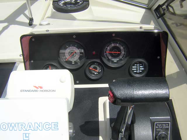
To the existing installation I added the SystemCheck gauge in the spring of 2005, replacing a voltmeter that was in that position in the original installation. The water pressure gauge is obscured by the other instruments. The speedometer is a Pitot tube device. Because of the Whaler Drive the Pitot tube was never in solid water, and as a result the accuracy of the speedometer was very poor. Also the boat had a top speed of about 40-MPH, so the 65-MPH speedometer choice represented perhaps too much optimism on the part of the original rigger. The speedometer will be eliminated in the new panel.
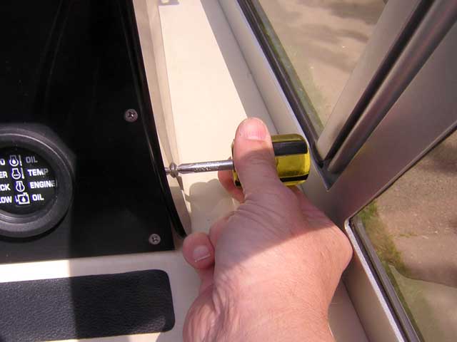
Removing the sun shade finally gave me a chance to use that stubby Phillips screwdriver I bought 25 years ago. Re-installing this screw turned into a 90-minute project. The original installation was an interference fit. I had to trim about 0.050-inch off the Plexiglas sun shade to get it to properly fit into place, then sand and buff the Plexiglas.
The existing dash panel with the sun shade removed shows the deck laminate extends about 5/8-inch behind the panel.
I had cleaned up the existing wiring from the original installation when I fitted the SystemCheck last season. There are still some airborne splices and a few other poor wiring practices that I wanted to clean up.
The new panel shape is a trapezoid with two rounded corners. It took careful cutting on a metal shear and some filing to get the 0.080-inch 3003 Aluminum sheet into this shape. The layout of the gauges was difficult to finalize. This layout has all gauges symmetrical to a horizontal center line which is located at the midpoint of the vertical dimension of the panel, The gauges are spaced equally from each other. There are 16 holes in the panel. The ten mounting holes were drilled by using the existing panel as a template to mark their location. In this way, the existing holes in the deck laminate could be re-used for mounting the panel.
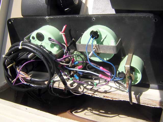
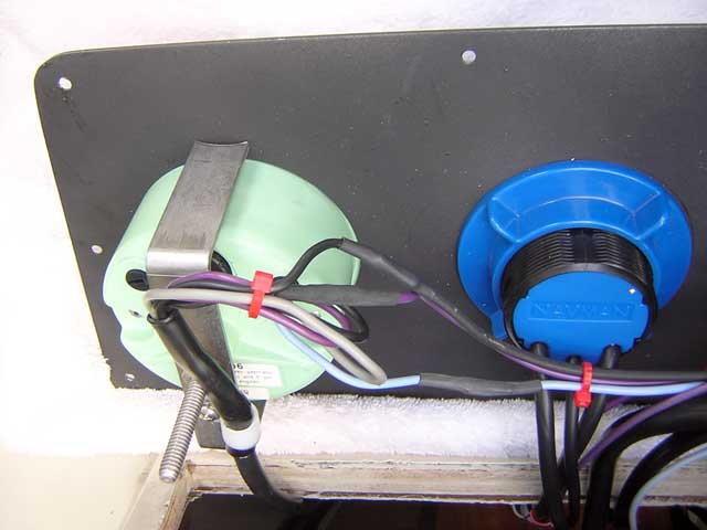
I drilled and tapped a 6-32 hole in the tachometer mounting bracket (left) to retain a cable clamp to holds the harness coming from the tachometer as a strain relief. I had to splice and extend the wires from the tachometer harness to reach the other gauges.
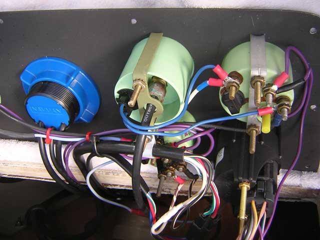
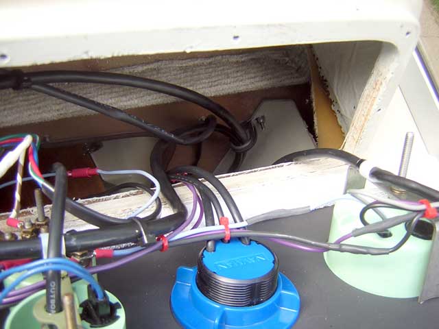
The rest of the wiring to the gauges is captive in the boat, and the connections cannot be made until the panel is in place. I added another cable clamp to hold the harness for the trim gauge. I also had to splice and extend the leads on that harness; it appeared that they had been cut off in the prior installation. The water pressure gauge had leaked a bit, and there was corrosion on its mounting hardware. Looking at this picture I just now realized that perhaps I should have mounted this gauge on the bottom row. If it leaks again the water will drip into the trim gauge below.
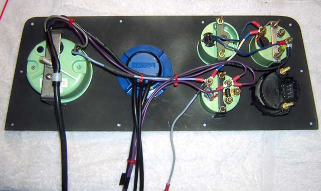
The rear panel wiring shows splices and extension of the original wires. The calibration control for the tachometer is at the top left, just behind the mounting bracket. Note the added cable camp to bear the weight of the harness.
On the dash interior I installed a large cable clamp into the bulkhead below the dash to retain the weight of the harnesses running up to the panel. The panel cut out exposes the wood core of the dash. This probably ought to be sealed with a coat of epoxy. Some resin has been brushed onto it, but it is not completely sealed.
With careful marking, center punching, and drilling, the hole alignment was very good. This was a gratifying result for an amateur metalworker like me.
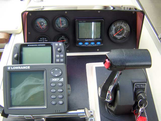
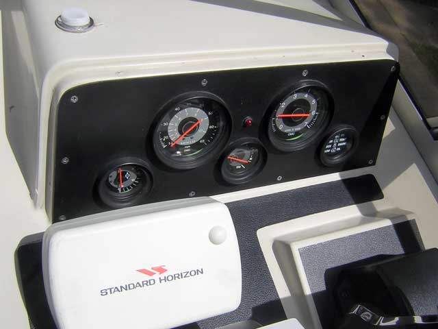
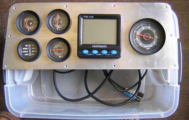
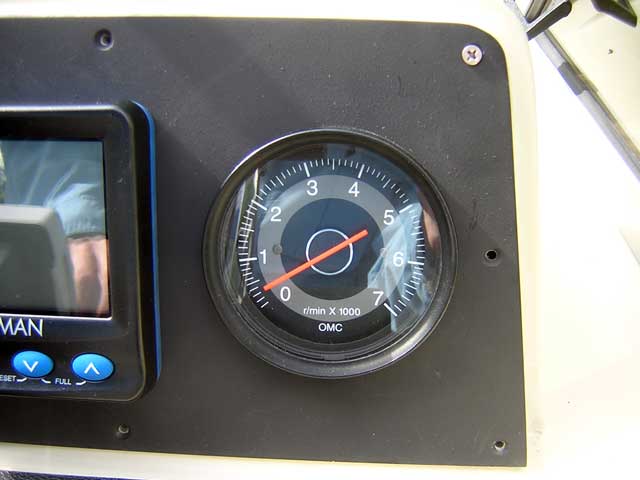
After two weekends of work, the new dash was finally in place. This view explains some of the layout decisions. The buttons on the NAVMAN 3100 FUEL monitor are easily reached. The NAVMAN can display two readings at once. The usual mode is to show SPEED and instantaneously computed MPG readings. The tachometer is right in front of the throttle. The water pressure and volt meter gauges are most visible. The trim gauge is somewhat obscured. The SystemCheck annunciator is partially hidden, but can be seen when needed if an alarm sounds.
Since this re-working of the instrument panel, I have added an additional gauge. In 2007 I installed an engine cylinder head temperature gauge. This gauge replaced the voltmeter in the upper left of the instrument panel. The voltmeter has been moved to the electrical panel on the lower portion of the helm console.
The total instrumentation now installed includes monitoring for the following parameters:
As you can see, for several parameters which are most important, there is redundant monitoring. In the future the instrumentation may be further expanded to include monitoring of a second cylinder head temperature. This is a simple addition as it involves only adding a second sensor and a switch; a single gauge could be used to monitor either sensor as selected. A paddle wheel sensor could be added to the SONAR to give secondary indications of SPEED and DISTANCE, as well as add a fourth SUM LOG function. The accumulation of fuel used, hours, and miles by the FUEL instrument has proven to be a very handy way to record and track the boat's use each season.
DISCLAIMER: This information is believed to be accurate but there is no guarantee. We do our best!
The page has been accessed times.
Copyright © 2008 by James W. Hebert. Unauthorized reproduction prohibited!
This is a verified HTML 4.0 document served to you from continuousWave
URI: http://continuouswave.com
Last modified:
Author: James W. Hebert
This article first appeared March 1, 2008.