Electric Starting Circuits
by James W. Hebert
This article describes typical electric starting circuits used in outboard engines and gives suggestions on diagnosing common problems. In order to make any meaningful investigation into electrical circuit problems, a basic understanding of electricity and a familiarity with making basic measurements of electric voltage is needed. If the reader lacks those skills, they should seek that knowledge before undertaking electrical diagnosis and repair.
Outboard engines are often fitted with electric motors for engine starting. In larger horsepower engines the electric starter motor is the only way to start the engine. Proper operation of the electric starter is therefore crucial. The circuitry which controls and actuates the electric starter motor is relatively simple, however it can be the source of frustrating problems. We examine the circuitry and offer some advice on diagnosis and repair of common problems.
The electric starter motor requires very high-current to operate. Because of this, it is operated by a control relay (commonly and hereafter called a solenoid) which is in turn controlled by an ignition switch. This arrangement divides the electric circuitry into two distinct segments, the low-current circuit associated with the ignition switch and the solenoid coil, and the high-current circuit associated with the starter motor.
Battery
When the engine is not running, the battery is the only source of electrical current available. All current for operation of the starter comes from the battery.
Low-Current Starter Circuit
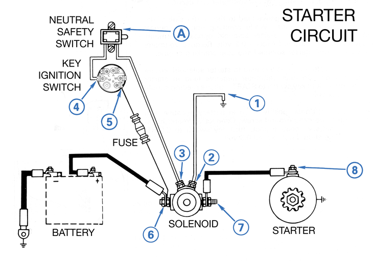
The low-current starter circuit is fairly complex and contains many likely sources of problems. The typical arrangement in most outboard engines is as follows: battery (positive terminal) voltage is supplied by the main outboard engine battery cable; an under-cowling fuse protects a branch circuit; the ignition switch controls current flow; current passes through a neutral safety switch in the remote throttle and shift controls; the current is applied to the solenoid coil; current returns to the battery (negative terminal) by the main outboard engine battery cable. Any discontinuity in the circuit will interrupt the flow of current.
The list below is typical of most outboard engine low-current paths. The actual circuit elements are show in bold; the remaining elements are wires and connections:
- Battery positive terminal post
- Ring terminal connector
- Main outboard engine battery cable (red)
- Ring terminal connector
- Terminal post under cowling of engine (often at the solenoid itself)
- Ring terminal connector
- Wire (red) to fuse holder
- Fuse
- Wire (red with violet stripe) from fuse holder
- Main engine harness connector
- Main engine harness wire (red with violet stripe) to ignition switch
- Ring terminal connector
- Ignition switch "B" terminal
- Ignition switch starter circuit pole
- Ignition switch "S" terminal
- Ring terminal connector
- Wire (yellow with red stripe) to neutral safety switch
- Neutral safety switch
- Wire (yellow with red stripe) from neutral safety switch to main engine harness connector, sometimes via another in-line connector
- Main engine connector
- Wire (yellow with red stripe) to solenoid
- Ring terminal connector
- Solenoid coil terminal
- Solenoid coil
- Solenoid coil terminal
- Ring terminal connector
- Wire (black) to engine block ground
- Ring terminal connector
- Engine ground terminal post
- Ring terminal connector
- Main outboard engine battery cable (black)
- Ring terminal connector
- Battery negative terminal post
Any of these (33) elements can cause the low-current circuit to fail.
High-Current Starter Circuit
The high-current starter circuit is very simple. The typical arrangement in most outboard engines is as follows: battery (positive terminal) voltage is supplied by the main outboard engine battery cable to the solenoid contactor; the solenoid contactor supplies current to starter motor; current flows back to the battery (negative terminal) on the main outboard engine battery cable. Any discontinuity in the circuit will interrupt the flow of current.
The list below is typical of most outboard engine high-current paths. The actual circuit elements are show in bold; the remaining elements are wires and connections:
- Battery positive terminal post
- Ring terminal connector
- Main outboard engine battery cable (red)
- Ring terminal connector
- Terminal post on solenoid
- Solenoid contact
- Terminal post on solenoid
- Ring terminal connector
- Wire (red) to starter motor
- Ring terminal connector
- Terminal post on starter motor
- Starter motor windings and brushes
- Terminal post or housing on starter motor
- Machine screw or wire to engine block
- Engine block
- Terminal post
- Ring terminal connector
- Main outboard engine cable (black)
- Ring terminal connector
- Battery negative terminal post
Any of these (20) elements can cause the high-current circuit to fail.
In the above enumerations of elements of the circuit, there is no accounting for any primary battery distribution or primary battery switching equipment. If your small boat has a battery distribution switch, any connections, wires, and controls associated with the battery distribution will have to be included as part of the starter circuit, and these elements will also have to be investigated as possible source of the problem.
Sources of Trouble
The Battery
Whenever there is trouble in the engine electrical starting circuit, the battery is the first element of the circuit to investigate. The load of engine starting is considerable, and the battery must be able to supply several hundred amperes of current while maintaining its voltage output. It is common that a battery will lack sufficient stored energy to be able to supply the current and voltage required for engine cranking, but the battery will have enough stored power to provide low-current demands, such as illuminating a few small lamps, powering low-current electronics, or operating the starter solenoid. To test the battery's condition, you must measure the battery voltage at the battery terminals. Connect the probes of an accurate voltmeter directly to the battery terminals and measure the voltage. A battery in good condition and with a full charge will have a terminal voltage of at least 12.5-volts. During cranking the voltage should not sag (drop) below 10-volts. (A separate article provides more information about determining the state of charge of a 12-volt lead–acid battery.)
Do not rely on voltage measurements provided by devices such as fish finders, GPS receivers, or dashboard voltmeters. You must measure the battery voltage directly at the battery terminals using a voltmeter with accuracy and resolution to 0.1-volt.
A common engine starting problem is a battery with insufficient power to operate the starter motor. When the load of the starter motor is applied, the battery terminal voltage drops, and the battery cannot supply the current required. A battery in poor condition with little current available will often exhibit a very pronounced drop in voltage when the starter motor load is applied. The voltage drop often will be so great that the solenoid coil will drop out, removing the starter motor load. This allows the battery voltage to rise, which in turn powers the solenoid coil. The solenoid connects the starter motor, dropping the battery voltage, and the cycle repeats. This produces a distinct chattering of the starter solenoid, a clear indicator of a battery problem. In other cases, the battery retains enough voltage to maintain the starter solenoid operation, but the battery cannot turn the cranking motor.
The remedy for a battery in a low state of charge is to re-charge the battery to full capacity, to replace the battery, or to connect a second battery in parallel. If the battery appears to be in proper state of charge and has good voltage output, you must look elsewhere for the source of engine cranking problems.
Conductors
As a general rule in electrical circuits, the electrical conductors themselves are not usually a source of trouble. That is, the actual wires are seldom a problem. Despite the general reliability of the wire conductors themselves, it is occasionally seen that due to ingress of water under the insulation of a wire, a copper conductor will become oxidized. A copper wire which has been oxidized or corroded will have a high resistance and will cause problems. Most of the low-current wiring is tinned copper, which is more resistant to corrosion. Most of the high-current wiring is bare copper, and it can be a source of corrosion if water (particularly saltwater) has intruded.
Connections
The connections at each end of a wire are very likely sources of trouble. Connections between conductors can be a particular problem in low-voltage circuits like a 12-volt circuit. The flow of electrical current at only a 12-volt potential can be interrupted by a very thin layer of insulation. Connections which mechanically and visually appear to be sound may in fact not be good electrical connections. A thin layer of corrosion or insulation may be preventing electrical current flow in a connection that looks perfectly normal. For this reason it is important to verify that all connections are electrically good and are conducting current. Connections are usually in the form of terminal posts with ring connectors or pin and socket connections. Check all connections to be certain they are conducting current without any voltage drop across them.
Many terminal post connections include special star washers which are intended to help provide better electrical contact by the penetration of their raised ridges into flat connector surfaces. Do not omit star washers where recommended. They are often used with ground connections to the aluminum engine block. The small points of the star washer will penetrate any surface oxidation on the aluminum. (Aluminum-oxide is not conductive.) Flat washers are also often used to help provide more electrical contact surface and to make a better mechanical connection. Do not omit or discard flat washers where needed. In some cases a single terminal post is used to bind several connectors. While this is not a recommended electrical practice, it is commonly seen under the cowling of outboard engines where space can be limited. In cases of multiple connections under a single terminal post, be certain that all connections are good. When connectors are layered on a terminal post, stack them in order of size, largest conductor on the bottom of the stack.
It is often seen that an electrical insulating rubberized paint is applied during original manufacture to protect electrical terminal post connections under the engine cowling. When these connections are later disassembled and reassembled, the insulating paint coating should be removed from all connector surfaces in order to assure that it does not interfere with the electrical contact between connectors. Once a re-done terminal post connection has been proven to be a good electrical connection, it can be re-coated with an insulating rubber paint.
Ring terminal connectors are used extensively to make electrical connections. In most cases ring terminals are only mechanically crimped to the wire conductor; they are not soldered. Check ring connectors to be certain they are making good contact with the wire conductor they are crimped to. On small wires it is a good practice to solder the ring connector to the wire in addition to crimping it. On large conductors, solder is often not practical due to the mass of the conductors and the large amount of heat needed to raise the wire to a temperature above the melting point of solder.
The connecting surface of ring terminal connectors should be free from any corrosion or insulating material. Gently clean the surface of ring terminal connectors with very fine emery cloth. Try to avoid using coarse abrasives on the connectors because you will remove the solder tin coating and expose the bare copper of the connector.
Some connections can be restored by spraying them with a solvent or cleaner. WD-40 is effective on many connections which are made in the open using terminal posts. A terminal post connection which is restored with a spray of WD-40 should be disassembled and thoroughly cleaned, otherwise the insulating corrosion may reoccur. Multi-pin connectors may require more sophisticated solvents in order to prevent any damage to the connector body material or seals. Check with your engine manufacturer for recommendations.
Controls: Switches and Fuses
Control devices in the circuit such as fuses, switches, or solenoid contacts, regulate the flow of current. Unlike conductors or connectors which are designed to always provide a path for current flow, control elements are designed to either provide a path or interrupt the path of current flow. Control elements are in the form of fuses, switches, or contactors. They are also sources of possible problems.
Fuses
The battery supply to the low-current circuit is fused. Check the fuse as a source of the problem before investigating elsewhere. The fuse is normally a closed circuit. The fuse interrupts the circuit only when excessive current has flown in the circuit. If you find the fuse has opened ("blown") you should also investigate the possible cause of the over-current situation which caused the fuse to actuate.
Switches
Switches are designed to control the flow of current, either allowing the current flow when closed or preventing the current flow when open. The ignition switch starter motor pole is a normally open switch which is only closed when the key is turned to the START position. When closed it permits current to flow in the low-current starter circuit. This switch can be exposed to water, and its contacts can become corroded. Check for proper operation of the ignition key switch starter motor pole.
The neutral safety switch a normally open switch which closes only when the shift lever is in the neutral position. It is designed to prevent engine cranking when the shift level is in any position other than the neutral position. This switch is mechanically linked to the shift control. Check that the alignment of this linkage is correct. The switch should have its contacts closed when the engine shift is in neutral; in any other position the switch contacts will be open. The switch may also be exposed to water, and it may a problem if it is corroded or damaged.
The starter solenoid contactor controls the flow of current in the high-current circuit. It is the only control device in the high-current circuit. The solenoid contacts are normally open, and they close when the solenoid coil is energized. Because of the high current flowing in the solenoid contacts and the inductive load of the starter motor winding, some arcing occurs. Arcing can lead to pitting of the contacts which causes high resistance to develop. A chattering contact (due to low battery voltage) often leads to excessive arcing and increase in resistance in the solenoid contactor. A solenoid whose contacts have become pitted and burned from arcing will often not make good electrical contact. This leads to a situation where the flow of current through the contactor is interrupted or limited to the point where the starter motor cannot operate, even thought the solenoid coil is receiving current and the contacts have closed. The remedy for this is to replace the solenoid. Fortunately, the solenoid is not too expensive, and they typically can be replaced with an OEM part of only $25.
Starter Motor
The electric starter motor can also be a source of trouble. The motor has brushes through which high current flows. In general, however, electric starting motors are usually reliable, and they are not the first place to look for the source of the problem. Eliminate all other possibilities before concluding the starter motor is defective.
Circuit Diagram
Most outboard engine service manuals will include an electrical diagram, either in schematic or pictorial form, that will show all details of the starting circuit. Such a diagram is a great aid in electrical troubleshooting of electrical starter motor circuitry. Even the most experiences electrical repair technician or engineer will be greatly helped by the guidance of a circuit diagram, and for the novice or inexperienced electrician, it will be crucial. If you are seriously interested in making electrical diagnosis and repair of your outboard engine, you will need an accurate circuit diagram.
Electrical Diagnostic Technique
Trouble in electrical circuits can usually be investigated quite effectively using just voltage measurements. Voltage measurements are very easy to make because they do not involve interruption of the circuit to insert the measuring device; a voltmeter needs only to be shunted across the circuit path to measure voltage. The flow of current in a circuit can be deduced by measuring the presence of voltage at various points in the circuit.
In a small boat electrical system all voltages are generally in reference to the battery negative terminal. If a voltmeter is connected with its negative lead bonded to the battery negative terminal, the positive lead of the voltmeter can then be used to measure voltage at various points in the starter motor circuit with reference to the battery negative. A long negative test lead will allow the voltmeter to be carried to many loctions on the small boat to test for voltage without disconnecting from the battery negative. The positive test lead of the voltmeter can then easily be placed at various test points to determine their voltage.
One method of electrical diagnosis is to begin at the source of electrical power and follow the circuit toward the load, checking for voltage where it is anticipated to be according to the arrangement of the circuit conductors and controls. Applying this method in a systematic manner will permit any discontinuity in the current flow to be detected. Because many of the connections in a small boat engine's eletric starter circuit are made on terminal posts which are exposed, access to these connection points is very easy, and voltage measurements can be taken without disturbing the connections. Use a test probe with a sharp point and apply it with enough pressure to penetrate through any surface layer of insulation. This will allow you to make a good electrical contact with the circuit at the measurement point. It is often necessary to make a tiny indentation into the metal of the connection point to get good electrical contact. This is especially true in the case of aluminum which may have a surface oxidation. Be certain your test probe makes good contact or else you will not make an accurate voltage measurement. If you suspect that a wire itself is causing a problem, you can usually pierce the wire's insulation with the sharp tip of the test probe and make contact with the wire itself.
Measurement of voltage in a circuit when no current is actually flowing can produce misleading results. Only a tiny current will be flowing in the circuit when measuring the voltage, and, as a result, there will be almost no voltage drop across any resistance in the circuit. When the actual load current flows, the voltage drop in the circuit may be much higher. Because of this, it is important to measure voltage in the circuit while under load.
Starter Circuit Check Procedure
Below is a test procedure for checking a typical starter circuit. This procedure will help isolate any problems in the starter circuit to a particular faulty component, wire, or connection.
Starter Circuit Check Chart, after one from an OMC service manual c.1992
| STEP | Procedure | RESULT |
Steps 1 through 6--Remove starter to solenoid cable from  to prevent starter engagement while making checks. to prevent starter engagement while making checks. |
| STEP 1 | Check voltage between ground and  . . | Remove black lead from ground at . Connect voltmeter between and ground. Turn key to START position. Voltmeter should show battery voltage. | a. If no reading, go to Step 2. b. If meter reads battery voltage, reconnect black lead to ground and go to Step 6. |
|---|
| Steps 2 through 6--Turn key OFF before connecting and disconnecting meter. Turn key to START after connecting. |
| STEP 2 | Check voltage between ground and  . . | Connect meter at . Turn key to START position. | a. If meter reads battery voltage, lead is open between and . b. If no reading, go to Step 3. |
|---|
| STEP 3 | Check voltage between ground and  . . | Connect meter at . Turn key to START position. | a. If meter reads battery voltage, solenoid is faulty. b. If no reading, go to Step 4. |
|---|
| STEP 4 | Check voltage between ground and  . . | Connect meter at . Turn key to START position. | a. If meter reads battery voltage, lead is open between and or neutral safety switch  is open or improperly adjusted. is open or improperly adjusted. b. If no reading, go to Step 5. |
|---|
| STEP 5 | Check voltage between ground and  . . | Connect meter at . Turn key to OFF position. | a. If meter reads battery voltage, check key switch. b. If no reading at , check for open lead or open fuse between and  . . c. Connect meter at . If no reading, check for open lead between and battery positive (+) terminal. If meter reads battery voltage, go to Step 7. |
|---|
| STEP 6 | Check voltage between ground and . | Connect voltmeter at . Turn key to START position. | a. If no reading, solenoid is faulty. b. If solenoid clicks and meter reads battery voltage, go to Step 7. |
|---|
| STEP 7 | Check voltage between ground and  . . | Reconnect starter to solenoid cable at . Connect meter at . Turn key to START position. | a. If meter reads battery voltage and starter motor does not turn, check starter motor. b. If no reading, check for broken cable or poor connection. |
|---|
FICHT and E-TEC Engines
On outboard engines with more sophisticated computer control systems, the engine starter motor solenoid control circuit may be influenced by the engine management module (EMM). The 2000 and later FICHT or Evinrude direct-injection (but not E-TEC) engines use a primary relay that in turn activates the starter solenoid. The relay is usually located on the aft port side of the engine near the EMM and is often tie-wrapped together with the engine's main power relay. The primary relay takes a moment to activate the starter solenoid, and in that interval the EMM is already booted up and records the ambient barometric pressure through the exhaust back pressure sensor tube. Experienced FICHT techs call this item the "dee-lay relay."
The primary relay is actuated by the yellow/red wire from the key switch, and the ground circuit is through a diode to the gray tachometer lead which at that moment is at ground potential inside the EMM. The relay makes contact, the current is directed to the starter solenoid, and the rest is history.
On the E-TEC engine, the solenoid control is also influenced by the EMM. A very small delay is added to obtain the barometric pressure. Also, the EMM checks to see if the engine is not already running. Due to the very low noise of an E-TEC when running an operator may try to actuate the starter on an already running engine. This circuit prevents it. Because of these additions, if there is a failure in the starting circuit on a FICHT or E-TEC engine, the problem could be in the EMM.
More Information
Additional articles in the REFERENCE section give details about marine wiring color codes and ignition switch wiring.
Summary
As detailed above, in a typical outboard engine with electric starting there are about 50 elements in the combined circuitry which could affect the operation of the starter. Any of these elements can stop the flow of electric current and cause the failure of the electric starter motor to operate. However, using simple electrical diagnostic techniques involving voltage measurement, isolation and identification of which portion of the circuit is causing the failure should be straightforward. The beauty of working with electricity is that it always obeys the laws of physics.
DISCLAIMER: This information is believed to be accurate but there is no guarantee. We do our best!
Copyright © 2008 by James W. Hebert. Unauthorized reproduction prohibited!
This is a verified HTML 4.0 document served to you from continuousWave
URI: http://continuouswave.com
Last modified:
Author: James W. Hebert
This article first appeared June 11, 2008.