When you want to add custom accessories to your boat, you should check with your Boston Whaler dealer or check with the factory before proceeding.
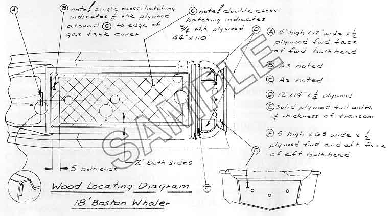
Accessories subject to stress, such as seats, consoles, etc., should not be attached except in areas that have wood inserts in the hull. Your safety and the safety of passengers could be affected by improper installations. Wood locating diagrams have been included in the owner's package of each new boat, or are available from the factory upon request. These diagrams are updated from time to time.
Fastening heavy accessories to the glass skin, either interior or exterior, is not recommended. Two problems could result: (1) the screws may tear out; or (2) the fiberglass skin may be pulled away from the foam core. If this occurs, further delamination may follow, leading to loss of needed hull strength.
Bonding items to the hull is also unsatisfactory. It is difficult to determine if a good bond exists, and the problem of parting the skin from the foam core remains critical.
The use of Molly or expanding bolts is not recommended. These could have the same effect of parting the fiberglass skin from the foam core. In certain cases, a "well nut" can provide good shock mounted fastening. Consult your local Boston Whaler Dealer.
When something has to be secured to the hull where there is no backing, special bolting techniques must be followed. This consists of spreading the compression force of the bolt over a large area. The reason is that a standard bolt and washer, when drawn tight, will have a tendency to crush the foam between the interior and exterior hulls. It will also lead to cracking of the fiberglass skin. The compression plate (both inside and out) may be fabricated from stainless steel, aluminum, or, in some cases, wood pads. Consult with the factory before such a job is undertaken.
When securing into wood inserts, or when bolting compression pads mentioned above, it is wise to use a number of fasteners rather than a few large ones. Stainless steel screws or bolts are preferred for their corrosion resistance and toughness.
When using screws to fasten components to the hull in areas where there is wood backing beneath, it is critical to drill a hole just through the glass surface large enough to accept the stem of the screw. Do not allow the drill to penetrate into the plywood beneath, for this is a soft material and needs no pilot holes at all. If the hole through the fiberglass were tight, the screw threads would pass through, but not the shank of the screw. The glass will not give and a continued tightening will strip the screw from the wood beneath.
All Boston Whaler 18 through 25-foot boats are equipped with ski eyes through bolted on the transom. These are the same eyes used for towing. A bridle equipped with a pulley and float attached to the ski eyes is recommended. The pulley allows the tow line to traverse from side to side as a skier jumps the wake, and the float is designed to prevent the line from sinking and tangling in the propeller.
18 GTX outboard and I/O models can be equipped with an optional ski pylon. This elevates the tow line and, because it is mounted forward of the engine, provides better control.
Elevated ski hitches and pylons which are available can be installed on most other 18 and 15 models. We suggest you consult your dealer or the factory before such installations are considered.
In the even your Boston Whaler must be towed by another vessel you should use the bow eye. DO NOT USE THE BOW BITT. The bow eye on all Boston Whalers is through bolted and area around the bow eye is reinforced.
If you are towing another vessel, use the ski eyes through bolted on the transom. DO NOT USE THE STERN CLEATS FOR TOWING.
When towing another vessel, the best method is to rig a bridal between the two ski eyes. The bridal should be long enough to allow a 45-degree angle coming from each eye. This will ensure even loads between the two eyes, center the towed vessel, and reduce yawing. DO NOT USE NYLON LINES FOR TOWING. They will stretch and should a fitting let go under pressure it will be projected like a missile. Tow line lengths may have to be adjusted so the towed vessel will ride comfortably in your wake.
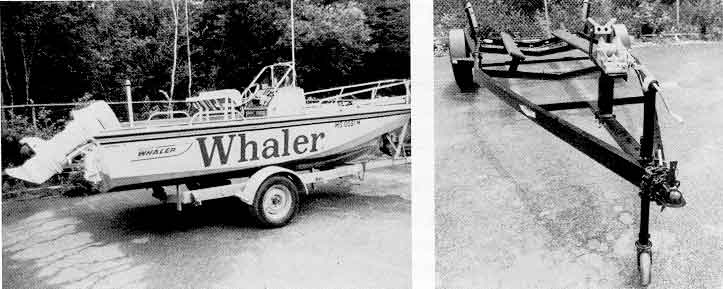
The keel of your Boston Whaler is the strongest area. The keel is designed to support the weight of the boat. For this reason, the trailer you select should contain center keel rollers to support the entire weight of the boat. Padded bunks should be located so they do not interfere with bottom spray rails and need only provide lateral stability.
Roller type trailers should not be used on Boston Whalers. Although this type of trailer is popular they can cause damage to your boat and to the foam sandwich construction. Roller trailers do not support the boat at its strongest point.—the keel. The rollers can cause a ripple effect on the fiberglass which could disrupt the bond between the fiberglass and foam core. In addition, rollers can put excessive pressure on molded bottom spray rails when the boat is being launched and retrieved.
Your trailer will be an important part of your boating pleasure. The trailer should match your particular Boston Whaler. Avoid over- or under-rating your trailer to your boat. Your Boston Whaler dealer can be of assistance in trailer selection and explaining features and benefits of various trailers. You should also consult him regarding safe trailering procedures and needed equipment.
Lifting systems vary depending upon personal preferences, space limitations, and physical factors. When selecting davits or lifting equipment, be sure the supplier and installer know where the lifting positions are on your particular Boston Whaler.
If you have any questions, consult your dealer, check with the factory, or consult your davit supplier.
CAUTION—If using a single point lifting system, the apex of the bridle must be high enough above the gunwales to provide lifting angles from the eyes to prevent distortion of the lifting eyes and stainless steel shanks. Avoid hooks which are too large for the eyes. If necessary, attach shackles to the lifting eyes to accommodate larger hooks.
These are equipped with a bow lifting eye and two stern lifting eyes on the interior of the transom.
This model is equipped with a bow lifting eye. Access to the bow lifting eye is through an access port under the bow cushions. Outboard models have two port eyes through bolted on the transom interior and I/O models have large "U" type lifting eyes on the outside of the transom.
These models are equipped with stern lifting eyes. On Outboard models rear lifting eyes are through bolted on the transom interior. On Sea Drive and I/O models "U" type lifting eyes are through bolted on the transom exterior. The optional bow lifting eye kit is required to provide forward lifting points on these models. This kit consists of two large pad eyes through bolted in the forward gunwale.
These models have stern lifting eyes through bolted on the transom interior on outboard models. Sea Drive and I/O models contain "U" type lifting eyes on the transom exterior. An optional bow lifting eye kit is necessary for forward lifting points. This kit contains two large pad eyes through bolted on the forward gunwale.
Outboard, Sea Drive, and I/O models are best lifted using slings. Transom lifting points are provided, but because of the bow deck configuration slings will be necessary for bow lifting.
DISCLAIMER: This information is believed to be accurate but there is no guarantee. We do our best!
The page has been accessed times.
Portions Copyright © 2005 by James W. Hebert. Unauthorized reproduction prohibited!
This is a verified HTML 4.0 document served to you from continuousWave
URI: http://continuouswave.com
Author: Adapted to HTML by James W. Hebert
This article first appeared February 5, 2005.