In most cases, the dealer will have installed your outboard motor following all the prescribed practices by Boston Whaler and the engine manufacturer. Should you be making the installation yourself, the following is a guide.
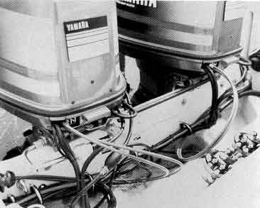
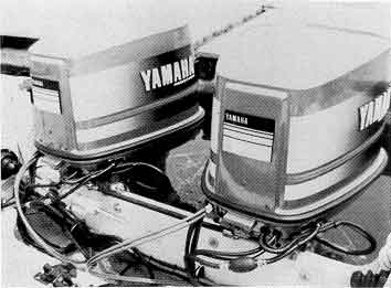
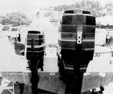
The large deep splash well just forward of the transom provides easy access to both upper and lower engine bracket mounting bolts. Dual engines must be installed in accordance with the instructions in the Boston Whaler dual engine tie bar kits which are available for each model.
This hull takes an extra long shaft (25-inch) engine for single engine installation, and a long shaft (20-inch) for dual engine installations. Dual engine Tie Bar Kits are available and should be used for dual installations to insure proper installation and operation.
This hull takes an extra long shaft (25-inch) engine for single engine installations, and long shaft (20-inches) for dual engine installations. Single engines should be raised 5/8-inch to 1-inch.
Dual engine tie bar kit (Part No. 15-0146-00) is designed specifically for all dual installations, both OMC and Mercury. Dual engine tie bar kit Part No. 15-0897-00 is designed for boats with optional hydraulic steering.
The engines in these models have been installed by Boston Whaler, or a dealer, in accordance with the engine manufacturer's recommended practices. The engine and out-drive units carry a warranty from the engine manufacturer.Be sure to fill out your separate engine warranty card. The warranty and operating instructions are packaged with your owner's information. Be sure to read this information thoroughly prior to operation. If you have any questions or problems, advise your Boston Whaler dealer and consult an authorized engine manufacturer representative.
All higher horsepower engines are equipped with power tilt and trim. The trim control is usually built into the engine control handle or mounted as a separate switch on the console dash panel. Power trim adjusts the engine angle to compensate for changing the load and sea conditions. However, improper use of power trim will affect engine efficiency, steering pull, cavitation, hull trim, and riding characteristics.
The proper use of power trim will enable the boat to plane faster and consume fuel more efficiently. Start with the engine trimmed in; this will depress the bow and lift the stern, allowing faster plane. Once on plane, the engine can be trimmed out to raise or lighten the bow. You will see how the boat planes much cleaner. This can be seen dramatically if you observe from another boat or the shore. Experiment with engine trim until the boat is riding comfortably and without steering pull. Over/under trimming will result in steering pull and a bow light/bow heavy running characteristic.
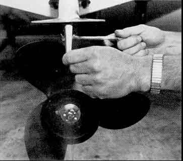
On larger Outboard motors, there is a steering trim tab located on the bottom of the cavitation plate, just aft of the propeller. It is adjustable and has been installed on the engine to correct for propeller torque.
Adjustment of the trim tab should be done after you've gone through the steps of proper tilt adjustment.
The boat should be operated with a normal load on board in a straight line. Incorrect trim tab adjustment will cause the boat to turn to the left or to the right when your hand are removed from the steering wheel. Be careful when removing your hands from the steering wheel; a tilt tab incorrectly positioned may cause the boat to turn violently.
To adjust the trim tab, loosen the securing bolts, as per the engine manufacturer's instructions, and move the trim tab in the direction the boat pulls. For example, if the boat pulls to starboard, move the trailing edge of the trim tab to starboard. Make these adjustments in small increments and test the results. The object is to create a "hands off straight line" steering condition for the normal operating speed. It is not possible to eliminate steering pull throughout the engine speed range.
Remember, tilt adjustment may affect steering torque as much as the trim tab. With Outboard engines equipped with power trim this becomes particularly important. When under way, experiment with trim settings to neutralize steering pull.
Under most conditions, the engine will be trimmed fairly close to the transom. However, once on plane, the engine can be trimmed slightly further away from the transom to obtain maximum efficiency. Experiment with trim until you obtain a comfortable ride based on the boat's load and sea conditions.
Large propellers on high horsepower engines normally create port list conditions on "V" hulls. If desired, the installation of trim tabs will correct this condition. The installation of a transom mounted transducer on the port side will also reduce port list.
In cross winds, it is not unusual for the boat to lean windward. You may notice this more in Revenge and Cuddy models due to their higher profile. Weight should be adjusted to trim the boat and take advantage of the "V" hull design and resulting softer ride. On boats with dual engine installations, engine trim can be used to correct listing conditions. Trim the engine on the low side in and trim the engine on the high side out to correct the list—also—adjust weight. Be careful not to trim the engine too far or cavitation will result.
To judge performance of your boat/engine combination, a tachometer is necessary. These are available from the engine manufacturer or are available as part of Boston Whaler's optional instrument panel. Some dealers are equipped with portable units, and all dealers should "Tach-Out" a new engine installation to make sure engine and boat are performing satisfactorily.
When selecting the correct propeller, tell your dealer what type of boating you will be doing. Will you be carrying a heavy load or light load? Do you need acceleration for water skiing or top speed with light loads? These are important factors for proper propeller selection.

The correct propeller diameter and pitch should permit the engine to attain maximum rated RPM with the anticipated load. The engine owner's manual will tell you the minimum and maximum operating RPM. Do not choose propellers which will allow the engine to exceed the maximum RPM.
The correct propeller will not only give you good performance but will save you fuel and reduce engine wear as well.
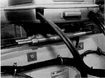
On larger boats 18-feet thru 22-feet capable of carrying engines of 200-HP and over, we install twin cable steering. In order to rig twin cable steering, it is necessary to obtain a twin cable adaptor kit and drag link kit from the engine manufacturer. In most cases your dealer will have rigged your boat and adjusted steering according to the steerer manufacturer's specifications.
On 18, 20, and 22-foot models equipped with dual engines, twin cable steering must be connected to the starboard engine. Our tie bar kits are specifically designed and recommended for all dual installations on 18, 20, and 22-foot models.
All Inboard-Outboard models are equipped with power assisted steering. Refer to the engine manufacturer's instructions provided with your boat for further information on maintenance of the power assist unit.
Optional on 18, 20, and 22 models and standard on all 25 models. The hydraulic steering system is filled, bled, and inspected at the factory. The following is furnished to aid maximum steering performance. Read the steerer manufacturer's instructions for more detailed instructions.
Periodic oil level check is required—particularly during the first five hours of operation. Oil level is checked through the cap on top of the helm just behind the steering wheel. Oil level should be checked on a monthly basis after break-in. Correct oil level must be maintained for proper operation of the steering system. See engine manufacturer's instructions.
If oil is low, add oil until correct level is reached. Oils used should be Sy-ten hydraulic fluid or Texaco Aircraft oil H015. Using a heavier oil will increase steering effort. Over filling could result in oil seepage from the vent in the fill cap. Seepage will continue until correct level is reached.
FAILING TO MAINTAIN ADEQUATE OIL LEVELS WILL RESULT IN LOSS OF STEERING. Should this occur, see your dealer or refer to the steerer manufacturer instructions for proper refilling and bleeding procedures.
To check for leaks in the system, pressurize by turning steering wheel to port and apply a 50-lbs. rim load on the wheel. Check all port connections. Turn wheel to starboard to pressurize and check all starboard connections. If a leak is detected tighten connection to a maximum of 15-ft-lbs. or call your dealer for assistance. Check hydraulic hoses periodically for signs of splits or abrasions. If any are detected have your dealer replace the hoses. Periodically lubricate all moving parts with a good quality marine grease.
In addition you should review the hydraulic steering manufacturer's instructions provided with your boat.
In most cases your dealer will have installed and adjusted engine controls. ENGINE CONTROLS ARE CRITICAL TO SAFE MANEUVERING. Therefore, they should operate smoothly and be properly maintained.
All controls, whether binacle (top) mount or side mount are equipped with a neutral safety switch which will prevent the engine from starting in gear. This is an important safety device and you should check to ensure it is working. If not, have it repaired immediately.
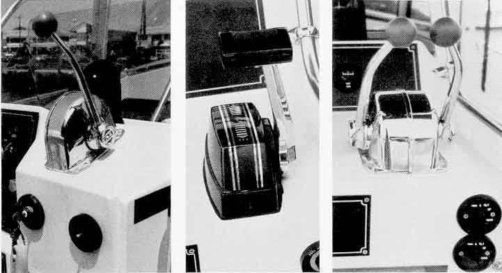
Control cables are plastic jacketed. You should ensure that all bends are gradual (5-inch radius minimum) and that there are no cuts or worn spots in the cable jacket. Tight bends will result in stiff operation of the controls. A break in the cable should be replaced immediately. Control cables should be checked every time you use your boat. If any abnormality exists, have the control system inspected by a dealer.
These models are equipped with an optional binacle (top) mount control. For single engine installation we offer either Morse single lever control or Morse single lever with power tilt and trim in handle. You should be familiar with the control features and operation prior to using your boat. Boats equipped with twin engines should be equipped with the optional dual lever controls. Separate tilt and trim controls are mounted on the console, not in the handles.
Controls on these models are similar to the Outrage Center Console models. Provisions for a binacle control have been designed into the dash in the form of a flat area. Refer to the Outrage section for operation and maintenance.
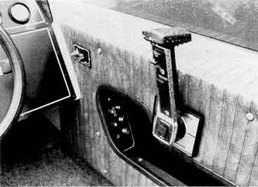
These models are designed only for side mount controls. On Outboard models the engine manufacturer's side mount control will be installed at time of engine installation. On Inboard-Outboard installations the side mount control is installed at the Factory. You should familiarize yourself with the features and operation of these controls prior to operation.
Controls on these models will be the same as those used in Outboard models.
As a general rule, batteries on Boston Whaler boats should be located aft for best weight trim. This is also the softest riding portion of the boat where there is less danger of the battery bouncing, being damaged, or spilling acid.
Provision has been made on all Boston Whaler for the installation of batteries. This is in the form of a special wood pad molded under the fiberglass floor to accept the screw fastenings of the battery hold downs. Represented below are installations, consult your wood locating diagram (included in Owner's package with boat) for exact location of the wood mounting.
Mounting the battery hold downs where they do not secure into wood will result in fastenings tearing through the fiberglass.
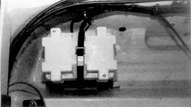
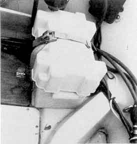
Batteries should always be enclosed in covered battery boxes as shown. It is important that a battery hold-down strap prevent the battery and battery box from moving to avoid wear on the gelcoat surface. We recommend the use of our battery box and heavy-duty, toggled, hold-down strap.
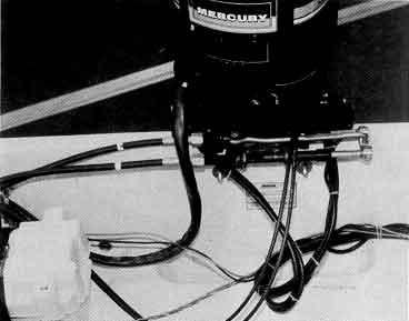
On Outboard models, single or Dual batteries should be located outboard in the engine splash well. Note: wood placement on the wood locating diagram. Using a single battery it should be mounted on the starboard side for easy access to the control tunnel and terminal blocks. This position will also offset the weight of a pony motor.
A single battery is mounted in the starboard rear storage compartment.
Single or Dual batteries should be mounted on the flat areas on each side of the of engine splash well. Note: there is wood molded into the splash well in this area. Using a single battery is should be placed on the starboard side for easy access to the tunnel and terminal block.
There is wood molded in under the floor on both sides of the splash well for battery installations. If a single battery is installed, it should be placed on the starboard side for easy access to the tunnel and terminal block.
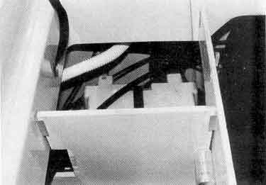
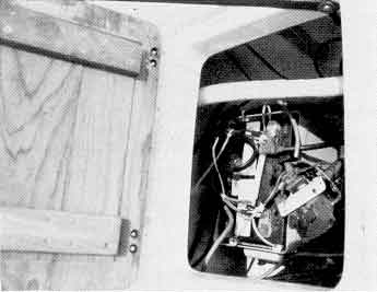
The battery is located under the starboard rear teak deck cover. The cover provides easy access for battery service without lifting the engine shroud cover on Inboard-Outboard models. If a second battery is installed it must be placed under the port rear teak deck cover. It is necessary to remove by cutting the bottom of the bait well for access. Consult your local Boston Whaler Dealer for specific instructions. On Sea Drive models batteries are mounted behind the rear deck teak access doors.
Wood is molded into both stern floor corners under the stern storage boxes for single or dual batteries. Easy access to the battery and storage area is through the access floor on top of the storage box. The battery should be mounted in a battery box and secured with our heavy-duty, toggled, hold-down strap.
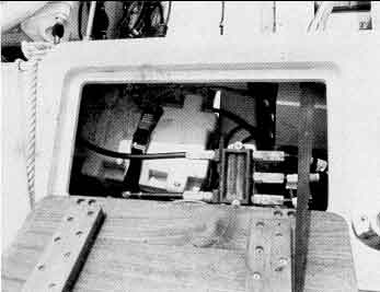
A battery should be mounted on the starboard side beneath the rear deck teak access cover. If a second battery is installed it must be placed under the port rear deck teak cover. It will be necessary to remove by cutting the fiberglass bottom of the bait well for access. Selector dials can be mounted on the outside of the Quarter box.
An auxiliary engine used for emergency power or trolling will not provide the boat sufficient power to plane and should be equipped with a very low pitch propeller to allow the engine to turn-up to its recommended RPM.
Because of its location off the centerline and its limited power, the use of a pony motor in heavy sea conditions can be difficult.
During rough running with the pony motor not is use it may be lashed in the up position to prevent it from inadvertently bounding out if its tilt lock and dropping down.
The transoms on these outboard models are 2-3/8th-inch in thickness for strength while using higher horsepower. Larger auxiliary engines (10-20 HP) can be clamped directly onto the transom. Lower horsepower engines may have mounting brackets which will not fit over the transom. These will require special mounting brackets which can be provided by your Boston Whaler Dealer. The 18, 20, 22, and 25 Outboard models require a long shaft (20-inch) auxiliary outboard motors.
Auxiliary engines should be fitted as far to port as the engine bracket permits. This will allow it to clear the main engine steering gear through its range of travel and will off-set the weight of the battery on the starboard side.
On these models it is necessary to use an auxiliary motor bracket for auxiliary engine installations. Auxiliary brackets can be thru-bolted on the transom in the wood area. In will be impossible to steer the auxiliary outboard with the bracket in the lowered position so it should be set straight ahead and the main engine used as a rudder.
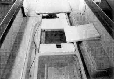
An aluminum fuel tank is permanently installed under the cockpit floor. A large hatch opening fastened with screws outlines the tank configuration. The tank is set into a molded fiberglass which is integral with the fiberglass skin of the hull. Fuel leakage, should it ever occur, will be contained in the fiberglass cavity.
In addition, under the center floor hatch cover are molded-in tunnels. They provide the channel for steering, control, electric, and accessory wiring cables from the battery and engine to the control console. These channels are separated from the fuel tank. It is normal for some water to accumulate in the tunnel and fuel tank area.
Water in these areas will drain to the aft sump and out via the manually opened drain when the boat is underway or the bilge pump is running if this option is installed. Your boat should be stored with the bow slightly elevated and all drains open. More individual hull drainage system information is provided in a separate section.
All fuel tanks are pressure tested for leakage prior to installation. Tanks are set on cushioned straps to support the tank and prevent abrasions. Space between the tank and the fiberglass cavity are filled with a gasoline-impervious foam. Large aluminum bars and flexible foam pads are placed on top of the tank to prevent any vertical movement. After the tank is installed and all fittings secured, it is again pressure tested to ensure the entire system is fuel tight.
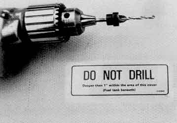
CAUTION: Do not drill into the fuel tank area. Consult your wood locating diagram if securing seats or other fastenings to the top tank cover. When drilling for screws or other fasteners is necessary, the drill should have a stop to prevent penetration greater than one-inch. Greater penetration may puncture the fuel tank. Consult your local Boston Whaler dealer.
Fuel withdrawal lines are plumbed to the starboard rear corner of the boat. On 18 and 20 foot models, fuel lines are located under the starboard teak gunwale board. On 22 foot models, fuel withdrawal lines are mounted in the hinged tunnel access cover. Earlier 22 models (with electric fuel gauges) have a single fuel withdrawal line from the tank to the twin hose connector under the access plate. Newer 22 models (with mechanical sight gauges) are equipped with dual fuel withdrawal lines from the tank. On twin engine installations, each engine should have individual fuel feed lines. On 25 foot models, with the single 140 gallon tank, two withdrawal fittings from the tank exit at the rear starboard quarter storage box. Earlier 25 foot models are equipped with two 70 gallon fuel tanks which are plumbed into a selector valve mounted on the starboard rear quarter box. On boats equipped with the single 140 gallon tank and twin engines, each engine should have individual fuel feed lines. Earlier 25 foot models can be equipped with a "Tee" fitting from the selector valve.
Connections from fuel withdrawal fittings must be air tight for proper fuel flow. Bard fittings and hose clamps have been installed to provide an air tight fuel hose connection to prevent air leaks.
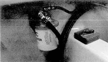
We strongly recommend installation of an engine manufacturer's approved fuel filter as a precaution against contaminated fuel and water, which will accumulate in any fuel system. Consult your Boston Whaler dealer. On tanks equipped with removable withdrawal tubes, a wide mesh large surface area filter screen is installed at the bottom of the withdrawal tube. Earlier tanks are not equipped with this clean out feature but do contain a mesh filter inside the barb fitting attached to the withdrawal elbow. Both are accessible through the access cover at the rear of the tank cover.
All models 18 through 25 feet are equipped with mechanical sight gauges. Earlier 22 foot models are equipped with electric fuel gauges. All fuel gauges will provide approximate reading of fuel level only when the boat is level or at rest. Remember, there always will be some fuel which cannot be withdrawn from the tank.
When filling the fuel tank, if oil is added directly to the tank it will settle to the bottom. Use a funnel (preferably with a strainer), mixing oil with gasoline, for proper oil mix. You will also find a funnel is helpful in keeping oil and gasoline off the teak gunwale board.
All models 18 thru 25 have plastic access covers on the fiberglass fuel tank hatch cover. These provide access to ground wires, fuel hoses, vent hoses. and withdrawal lines.
Whenever these are opened (by inserting a screwdriver into the slot and twisting), the neoprene "O" ring around the cover should be cleaned and greased.
It is not unusual for condensation and moisure to be present under the gas tank cover. This will cause condensation to occur under the clear mechanical sight gauge cover. The area of gas gauge should remain clear. If it does not, remove the clear cover and adjust the two screws with springs to raise the dial slightly so it just touches the clear cover.
To reduce condensation from occurring during storage or when the boat is not used for long periods, leave the tank or tanks full and add dry gas. An additional can of dry gas should also be added in the spring. Store the boat with the bow elevated and all drains open.
Dealer installed fuel filters should be changed periodically. At least once a year, access ports should be removed for inspection of vent hose ground wire connections, sender connections (22 foot models), fill hose, withdrawal hoses, and hose clamps. Remember to clean and lubricate the access "O" ring prior to reinstallation.
If silicone around the hatch cover becomes loose, it should be replaced to prevent debris and dirt from building up in the joint, making wash-down easier.
All Outboard models, 18, 20, 22, and 25, are self bailing. This means if the rear sump drain is left open, water will not come above the floor level. Individual fishwells and lockers may accumulate some water, but if the drains are left open water will [exit] and drain dry when underway.
These models have five drain tubes (four on GTX Outboard)—three in the transom splashwell, one in the starboard aft floor sump, and one in the bow locker (not on 18 GTX Outboard).
The three transom splash well drains should be left open at all times. The sump drain, when left open, will allow water to enter the sump and tunnel area. The level will depend on power option and weight. Additional rain or washdown will exit because of the hull buoyancy. The fuel tank area will drain to the sump. If the optional bilge pump is installed and left on automatic, the sump drain should be plugged to prevent constant running of the pump. The bow anchor locker drains directly through the hull via its own drain tube. We recommend leaving this drain plug out to allow rain water to exit.
This model has three drains. The rear engine well drain is plugged from outside. This drains the engine well compartment only and should remain closed except for storage. An automatic bilge pump and float switch are installed in the engine well. IT IS YOUR RESPONSIBILITY TO CHECK THE OPERATION OF THE ENGINE WELL BILGE PUMP FREQUENTLY as this pump is designed to precent water from damaging the lower parts of the engine should water enter the well. The starboard aft floor sump drains the cockpit floor. A connecting transfer drain from the sump to the port cockpit floor is designed to prevent water from accumulating on the port side of the engine well.
There are five drain tubes on all 20-foot models. The three drains on the transom drain the engine splash well and should be left open at all times. The starboard aft floor sump drain, under the teak cover, drains the cockpit. With the plug out, some water will accumulate in the sump and tunnel areas which will quickly drain dry once underway. If the optional bilge pump (standard on Revenge models) is installed and left on automatic, this drain must be kept closed to prevent constant running of the pump. Any water in the fuel compartment will drain to the sump compartment.
The two bow compartments have a single drain located in the rear fishwell. You will note the forward compartment has a shelf to keep anchor and rode separate from and above the water level of the fishwell On Outrage models this drain can be left open. It should be closed on Revenge models.
All 22 Outboard models have eight drain tubes. A single transom splashwell drain has a ball check valve on the outside of the transom. The check valve helps reduce the inflow of water when backing down. The transom splashwell drain should be open at all times.
The fishwell has two drains. The drain between the fishwell and the splashwell has a check valve. It is intended to be left open to automatically drain the well of rain and washdown water when underway. This drain must be closed when keeping fish to avoid fouling the check valve. The second, through bottom drain, empties the well of fish foul water once underway.
The cockpit floor drains directly thru hull via the starboard aft floor sump. The fuel tank area drains to this sump.
The cockpit floor drain should be left open unless the optional bilge pump (standard on Revenge and Cuddy models) is installed. With the drain open, water will accumulate in the sump and tunnel, the level depending on power options and weight. Water from wash down or rain will stay below the floor level because of hull buoyancy. With the bilge pump installed and left on automatic the sump drain must be closed to prevent constant running of the pump.
Each bow locker has a drain. On Outrage models the forward anchor locker should be left open. The bow fishwell drain should be left closed as it is guttered to prevent entrance of rain water. Rope locker drains can be left open.
On Revenge and Cuddy mdoels all bow locker drains should be closed.
The bow locker drains on these models are the same as Outboard models.
Inboard/Outboard models have a rear enginewell drain. This drains the enginewell only and should remain closed except for winter lay-up. An automatic bilge pump and float switch are installed in the enginewell. IT IS YOUR RESPONSIBILITY TO CHECK THE OPERATION OF THE ENGINEWELL PUMP FREQUENTLY as this pump is designed to prevent water from damaging the lower parts of the engine should water enter the enginewell.
There is a connecting transfer drain from the port cockpit floor to the main cockpit starboard aft floor sump drain. This is designed to prevent the build up of water on the port side of the enginewell. Outrage models may be equipped with an optional bilge pump in this sump. Bilge pumps are standard on Revenge and Cuddy models. If the pump is left on automatic the sump drain must be plugged to prevent constant running of the pump. Both I/O and Sea Drive models will self bail due to hull buoyancy if the cockpit sump drain is open.
Sea Drive models contain three drains on the transom. The lower center transom drain located in the depression (splash well) in the center of the floor behind and under the stern deck can be left unplugged. There are two flapper type valves located at the floor level. These will automatically drain large quantities of water from the cockpit floor. The starboard aft floor sump drain will also drain the cockpit and fuel tank area. If a bilge pump (optional on Outrage models and standard on Revenge and Cuddy models) is installed and left on automatic, this drain should be closed to prevent constant running of the pump.
All 25 Outboard models contain eight drains. The single engine splash well drain should be left open at all times.
The rear fishwell has a separate through hull drain tube. If left open water will accumulate in the well which will drain once underway. If left closed, overflow drains into the starboard aft floor sump which if left open will drain because of hull buoyancy.
The starboard aft floor sump drains the cockpit and is located under the teak cover on the floor. Water from the fuel tank area drains into the floor sump. Unless a bilge pump (optional on Outrage, standard on Revenge, Cuddy, and Frontier models) is installed and left on automatic, we suggest leaving this drain open.
25-foot hulls are equipped with an additional port side rigging tunnel. A separate through hull drain is located under the teak cover on the rear port floor. This drain can be left open. If closed, overflow water will exit the sump via a transfer drain to the main sump drain on the starboard side.
Each of the four bow lockers has a drain. On Outrage models the forward anchor locker drain should be left open. The bow fishwell drain located under the teak access cover should be left open as it is guttered to prevent entrance of rain water. Rope locker drains can be left open.
On Revenge, Cuddy, and Frontier models all bow locker drains should be closed. The cabin floor drain located under the teak access cover should only be open when underway to remove cabin washdown water. Note that this drain is under the overhanging cockpit floor on some cabin models.
The forward cabin drains on these models are the same as those on Outboard models. Review the preceeding information.
The rear enginewell drain on O/I models is plugged from the outside. This threaded drain plug should be left closed as it drains the enginewell only for winter lay-up or storage. An automatic bilge pump and float switch are installed in the enginewell. IT IS YOUR RESPONSIBILITY TO CHECK THE OPERATION OF THE ENGINEWELL PUMP FREQUENTLY as this pump will prevent water from damaging the lower parts of the engine should water enter the well. I/O and Sea Drive models contain a transfer drain from the port side tunnel to the starboard main sump. Therefore the drain tube under the port side rear floor teak cover can be left open.
The starboard aft floor sump drains the cockpit floor and fuel tank area. If left open, water will accumulate in the sump and tunnel. Water from the wash down or rain will stay below floor level because of hull buoyancy. With the bilge pump installed (optional on Outrage models and standard on Revenge, Cuddy, and Frontier models) and left on automatic, this sump drain must be closed to prevent constant running of the pump.
Sea Drive models drain systems are similar. However, Sea Drive models are also equipped with two flapper type drain openings through the transom. These automatically drain large quantities of water quickly should the cockpit floor become flooded.
DISCLAIMER: This information is believed to be accurate but there is no guarantee. We do our best!
The page has been accessed times.
Portions Copyright © 2005 by James W. Hebert. Unauthorized reproduction prohibited!
This is a verified HTML 4.0 document served to you from continuousWave
URI: http://continuouswave.com
Author: Adapted to HTML by James W. Hebert
This article first appeared February 5, 2005.