Control of a vessel's navigation lights is often accomplished by a single switch with multiple positions. On small boats there generally are only three positions: OFF, ANCHOR, and UNDERWAY. Electrical schematic diagrams are presented to show the usual wiring for control of the lamps which will produce the proper display of navigation lighting.
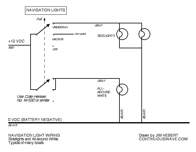
Control of the NAVIGATION LIGHTS on most boats using sidelights and an all-round white lighting scheme is typically accomplished with a single switch, usually a marine-grade three-position push-pull switch. The positions are OFF (pushed in all the way), ANCHOR (pulled out to first stop), or UNDERWAY (pulled out all the way). The ALL-ROUND WHITE light is shown in both ON positions; the SIDELIGHTS are shown only in the second ON position. On smaller boats the SIDELIGHTS are often combined into a single lamp and carried on the bow instead of two separate lamps as shown.
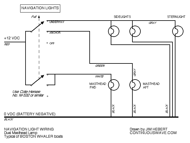
Some BOSTON WHALER boat with a center console employ a more complex scheme for their NAVIGATION LIGHTS using a dual-bulb masthead lamp where each lamp illuminated a different sector, separate sidelights, and a sternlight. These are also often controlled with a single switch, again a marine-grade three-position pull-push switch. The positions are OFF (pushed in all the way), ANCHOR (pulled out to first stop), or UNDERWAY (pulled out all the way). The dual-bulb lamp fixture which is normally located at the center console serves a dual purpose as both a MASHEAD LIGHT when underway (only forward-facing sector is illuminated) and as an ANCHOR LIGHT when at anchor (both forward-facing and stern-facing sectors illuminated). The SIDELIGHTS and STERNLIGHT are only illuminated when underway.
Note that the Boston Whaler installation of navigation lamps makes use of a specialized lamp that serves a dual purpose: it can be a masthead light when only the forward sector is illuminated; and, it can be an anchor light when both forward and aft sectors are illuminated. This special lamp could be replaced by two separate lamps, one a masthead light and the other an anchor light. If that is done, the simplest control wiring would be to use two switches, one to control the running light and a second to control the anchor light, or a single switch with two ON positions like the COLE-HERSEE M-531.
The Cole-Hersee company for many years has made several specialized switches whose action and circuitry as particularly useful for controlling navigation lighting on boats. In addition to the information presented below, use of Cole-Hersee switches in control of navigation lightning is described in detail in a seaparate article. It has also been noted that WEST Marine is now carrying these switches as a stock item.
A specialized COLE-HERSEE switch (Model M-532) is often used to control the display of navigation lights on small recreational boats when the dual-purpose lamp is used for both masthead and anchor lighting.
Details of the COLE-HERSEE M-532 switch are shown in their websitee. The switch is described as a three circuit switch. From the nomenclature used, I infer the following:
I can summarize the switch as follows:
There is no guarantee that the color of the insulation on the wiring associated with the navigation lamps on a particular boat will match the colors I show in my diagram above. Rather than just relying on the wire insulation color to establish what lamp circuits are fed by a particular wire, perform this procedure to identify the function of each wire in the navigation lamp circuits:
There is a somewhat simpler switch made by Cole-Hersee, their M-531, that sometimes is used for some boat electrical circuits. This switch is a three-position switch, as follows: OFF, ON-1, ON-2. The switch has three terminals, marked B (for battery), A (for first circuit), and H (for second circuit). The M-531 switch works as follows, as best as I can tell from the information furnished by Cole-Hersee about it:
If that is how the switch works, there is no way to use this switch to control sidelights and a white all-round light so that only the white all-round light shows in ON-1 position and then both the white all-round and sidelights show in ON-2 position. It just cannot be wired to perform that function. An M-532 is needed. The M-531 can control navigation lighting if the anchor lamp is complelely separate from all the running lights lamps and no lamps are shared between the two functions. For more details see a separate article that describes this wiring.
In complete contradiction to the above, it has been reported by others that you can use an M-531 to control sidelights and a white all-round light as would be desired. I seriously doubt this to be true. In order for that to be true, the switch action would have to be different than Cole-Hersee describes. There is no reasonable basis to assume the switch works differently that the manufacturer describes, so I assume these reports from other are wrong and should be ignored. The M531 switch could be made to work if a diode is used, but inserting a diode creates a voltage drop. Incandescent lightbulbs have a very rapid decrease in light output when voltage is decreased, so inserting a diode is a poor approach to controlling incandescent lightbulbs. Creating some special wiring to use a switch that is actually not suited for the purpose seems like another poor approach. Get the M532 switch.
DISCLAIMER: This information is believed to be accurate but there is no guarantee. We do our best!
The page has been accessed times.
Copyright © 2006 by James W. Hebert. Unauthorized reproduction prohibited!
This is a verified HTML 4.0 document served to you from continuousWave
URI: http://continuouswave.com
Last modified:
Author: James W. Hebert
This article first appeared June 07, 2006.