On-Deck Fuel Tanks
I am very pleased to present this
article by Robert Schmidt (aka
ratherwhalering) on fuel tanks.
Rob has done an excellent job in compiling this information
and it is a welcome addition to the Reference collection
Introduction
In most Boston Whaler boats of less than 18 feet in length there
are no built-in fuel tanks in the interior of the hull.
For many of the smaller boats, the usual 6-gallon portable
tank provided with most outboard motors has adequately served.
For the 17-Montauk model in particular, because of its outstanding
abilities for its size, a greater fuel capacity is often required
to satisfy the demands of its use.
This article discusses in detail
the installation of a Pate Plastics tank on a
Boston Whaler 17-Montauk. In addition information is provided
about other tanks, their dimensions, and their vendors.
--Jim Hebert
On Deck Fuel Tanks
By Robert Schmidt
UPDATE, August 2008
Please note: Pate Plastics has ceased to manufacture fiberglass fuel tanks. Tempo Products has ceased to manufacture plastic fuel tanks.--Jim Hebert
After problems with the two red 12-gallon OMC tanks in my 1987 17-Montauk,
I finally decided to upgrade to a single large tank. I had seen Pate tanks
before and was already predisposed to their matching "Desert Tan" color and
good looks. I did a lot of research, and finally decided on a Pate C27
fiberglass tank.
PATE PLASTICS Brand
Pate Plastics offers four tanks for the Montauk. Their model number is
designated by the capacity in gallons.
Table 1: Pate Plastics Fuel Tanks
| MODEL |
C18 |
C21 |
C24 |
C27 |
|---|
| CAPACITY |
18 |
21 |
24 |
27 |
|---|
| HEIGHT |
9 |
10 1/4 |
11 3/4 |
12 7/8 |
|---|
| WIDTH |
19 |
|---|
| LENGTH |
30 1/4 |
|---|
| PRICE |
$357 |
$363 |
$382 |
$389 |
|---|
| Capacity in gallons; dimensions in inches. Prices as of 6/2002. |
You can order directly from Pate:
Pate Plastics, Inc.
360 N.W. 71st Street
Miami, FL 33150
TEL: 305-754-0896
FAX: 305-253-6611
It will cost you $443.50 including shipping for the C27 and the mounting
kit. The tank is $370; the kit is $48.50 and the shipping is $25.00. The
tank is available in "Desert Tan" to match the Montauk's hull color, but you
must specify this color when ordering.
Installation Details
There are a few things to know about the Pate tanks. First, and foremost,
it is a one piece tank that may actually fit inside the factory deck pads,
with a slight modification. The Pate Tank has a thin, raised 1/2-inch
fiberglass molded edge around its entire base. The factory deck pads are
designed for two separate tanks, and if the one piece tank is mounted inside
the factory deck pads, the inner lip of the pad intersects the outer edge of
the tank. The solution I have observed is to trim 1/2-inch section of the
inside edge of the lips of the deck pads.
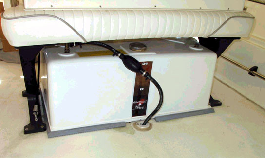 |
1999 17-Montauk with C24 Pate Fuel Tank
The tank fits in the factory deck pads,
with the inboard lip of the pads removed on either side of the thru
hull fitting. The tank completely covers the old bilge access hole,
and a new one has been drilled and capped.
There is just enough clearance to access the tank filler.
If this were a C27, I doubt you could fill it without hinging the seat.
PhotoCredit: Robert Schmidt |
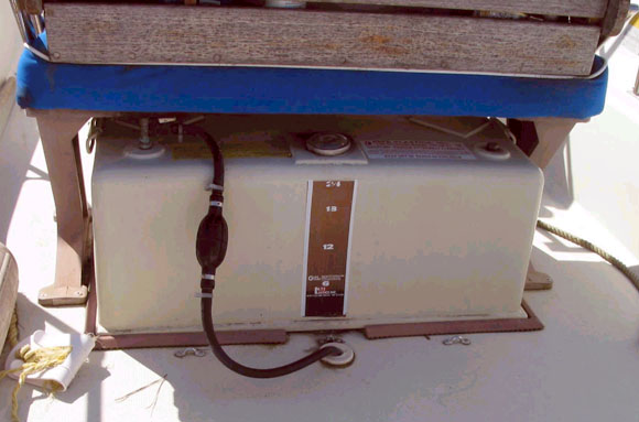 |
1982 17-Montauk with C24 Pate Fuel Tank
Again, the bilge access hole is covered and a new one has
been installed. The factory deck pads do not appear to have been moved,
and eyelets have been mounted directly to the deck for straps.
This tank is even easier to fill than the one shown above
because it is mounted farther aft.
PhotoCredit: Robert Schmidt |
Choosing Location
I have observed that the C27 cannot be filled, due to its height, when
mounted in the factory deck pads. The clearance between the bottom of the
seat and the top of the tank is too small. There are a few options I know
about. One is to hinge the seat, as discussed below. Another is to move
the factory deck pads forward, exposing a section of the original bilge
access hole. The other is to remove the factory deck pads and move the C27
slightly aft. There are considerations with each.
I selected not to hinge the seat, but to relocate the tank slightly aft.
The pros and cons I considered are these. In favor of moving the tank aft:
- The outer edge of the tank made complete contact with the floor
of the boat. With the pad installation, there is a 2-inch gap right
down the center of the tank. While this would be great for
water drainage, I was worried the tank might fatigue or split over time.
- I was concerned about the integrity of a hinged seat.
- The tank is easier to fill without a hinged seat.
Weighing against moving the tank aft:
- less deck space aft;
- more weight aft;
- more exposure to sun and elements.
In retrospect, after hearing from several forum members,
I might now opt for an installation in the factory deck pads with a hinged seat.
First, the installation is easier; you don't have to remove the factory deck pads.
Second, there is less weight aft, a consideration when repowering with
today's heavier 4 stroke engines. Third, there is more aft deck space.
I decided not to move the factory deck pads forward because I liked having
ample foot room between the console and the front of the tank. In order to
expose a portion of the existing bilge access to accommodate a fuel line,
the C27 would be so far forward that it interfered with my piloting space.
Of course I could move the console forward, but this requires moving the
cooler and chocks too. At least one forum member (Rex) has done this; he
removed the entire interior, refinished the gel coat, and then remounted
everything to his liking. This allowed him to move all the components
forward, and expose the original bilge access for the fuel line. Pictures
are available on Page 41 of Cetacea. What a boat!
Installation
My project started with the removal of the factory deck pads. The factory
deckpads are pop-riveted on. To remove them, I used a
small drill bit (maybe 1/8-inch) and drilled out the center of the pop rivet.
I then pulled the rivet straight out with pliers. This sounds much easier
than it is, so I had to be patient. Believe me, do not over drill these
suckers because you can split the outer sheath, and end up with a mess!
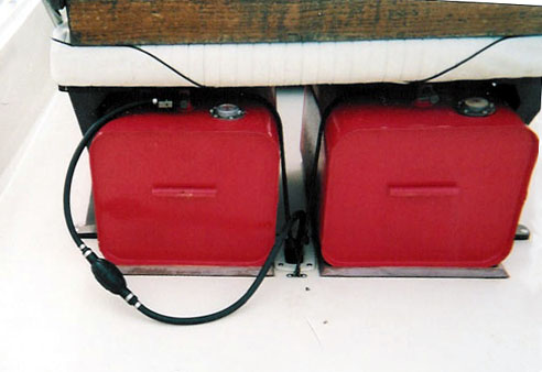 |
1987 17-Montauk with Two 12-gallon Tanks
With a new C27 tank in the old factory deck pads,
the bilge access will still be covered.
PhotoCredit: Robert Schmidt |
Once all the rivets were out, I cleaned the rivet holes with a drill bit
and the area around the holes with acetone. I then filled the holes.
Experts suggest using wood dowels, epoxy, then gel coat;
I just used 5200 (quick cure) in a syringe, and then cleaned up the surface
with solvent. When I positioned the tank, only the rear holes were covered.
The front holes were just barely exposed. I decided to use one piece teak
strips instead of the mounting blocks, so the old (front) holes were not visible. If you're not sure, position the tank first, then if there are exposed holes, consider filling with dowels, epoxy, and gel coat.
Now the tank. I had to position it so that the tank's filler hole is
accessible from the rear of the Reversible Pilot Seat (RPS);
the seat of the RPS gets in the way. I simply removed the old center strap eyelets and snuggled the rear inside edge of the tank rim against the old bilge tube access plastic flange. I actually cut the aft edge of the plastic flange 1/4-inch (to flatten it out) with a razor and a metal square. I squared the tank and marked its position with pencil. My old bilge tube access was now covered by the tank. I removed the tank, and decided where I wanted the fuel line hole to enter the bilge tube. I decided that 1.5-inch from the edge of the tank was sufficient.
I left space between the tank and the planned access hole for the mounting
hardware. Now the tricky part. I went to West Marine and bought a threaded
"mushroom" thru hull fitting that would accommodate my 5/8-inch fuel line. The
mushroom's stem needed to be a good 2-inches long. I then bought a hole saw that
makes a circular hole the exact size, maybe a little smaller, as my hull
fitting. The hole saw comes with a 1/4-inch pilot bit.
Next I tried to find the exact center of the bilge tube where I wanted
my new hole. Guess what? The center of the plastic access flange may not
accurately represent the top dead center of the bilge tube. I used the
flange to measure where to cut the hole, and it was slightly off. I later
realized that the flange was off center. Maybe I should have removed the
flange, found the center, then found the center at the aft access, and
chalked a straight line.
I then took a break, sipped a beer, and returned to position and measure
everything again.
I then took a deep breath, and drilled the fuel line hole. I cut through
the gel coat, the fiberglass, the wood backing, the foam core, and the top
of the aluminum bilge tube. I was careful not to drill too far, and into the
controls cables and electrical wires already inside the bilge tube. In
fact, after I started the big hole, I shortened the pilot bit and continued.
[Excellent idea!--jimh.] Once I had the hole drilled, the hard part was over.
I took a round file and feathered the gel coat around the fuel line hole.
This is so the gel coat would not crack. Whenever I drill a hole in gel
coat, I always feather the gel coat. When a screw is inserted into gel
coat, it cracks. There is no flexibility in gel coat at all, whatsoever.
It is like trying to screw into glass. For example, when I drilled the
holes for the mounting blocks (strip), I drilled the holes with a drill bit
slightly smaller than the diameter of the threads of the screws. Once I had
all the screw holes, I took a large drill bit (there is an actual bit called
a "reamer" that is meant for this, but you can use a larger bit to
accomplish the same thing) I drilled the top of the hole until the spoils
turned from tan to green, This only took 4-5 rotations of the large bit.
The gel coat is very, very thin. The object is to slightly broaden the gel
coat but not the fiberglass underneath, to which the gel coat is adhered.
The screws threads will now bite into the fiberglass and wood underneath the
gel coat, but not the gel coat itself. I added a touch of 5200 in the new
hole to seal.
I then measured the depth of the fuel line hole, and cut the length of the
thru hull fitting to just beyond the top of the bilge tube. With the thru
hull cut to size, I was ready to seal the fitting. The fitting must be sealed.
Experts say epoxy, I used 5200 because it is less messy. I gooped it in the
hole and on the thru hull threads. I then screwed the threaded, mushroom
thru hull fitting into the hole. My thru hull fitting was really hard to
thread into the hole; I used a large, flat file to turn the thru hull
fitting. You'll understand when you see thru hull fitting.
Now the easy part. I positioned the tank, and prepared to install the
mounting blocks, planning to drill the holes as described above. I decided
against a rubber pad or dry dock type of pad. This was due largely to
vertical space considerations, and because I wanted the mounting blocks to
snug right up to the lowest point of the tank. I felt that if I elevated
the base of the tank with a pad, the blocks might not be tall enough to
prevent it from sliding around. The added benefits of a tank pad are water
drainage and reduced abrasion on the non-skid. I might consider it if I had
installed the C24.
The mounting blocks are just that: 2-inches long, 1/2-inch square.
The blocks are pre-drilled, and the kit includes the screws, washers,
bungee cords, and eyelets.
I opted for one long strip of teak instead of the blocks. The
hardware was useful, though. The standard mount is two blocks on the front
and back corners, with eyelets for the bungee, and one block on the port and
starboard side to prevent lateral movement. I did the same sort of thing,
but used teak strips instead of the blocks.
After all was said and done, I put the tank in, mounted the hardware to the
deck floor, and strung the bungees. It looks great! I had to put an 1/4-inch
elbow fitting in the gas pick-up tube because the quick connect I was using
was too long and wouldn't fit under the seat. Then I ran a new gas line
through my new hole, and out the back, to the engine. I later mounted a gas
filter and relocated the primer bulb, but that is another story!
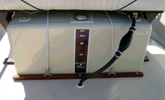 |
Rob's 1987 17-MONTAUK with 27C and Teak Hold Down Strips
The end result of the process described above!
The original deck pads have been completely removed to enable
better clearance in the tank height and to permit flexibility
in fore-and-aft location of the tank.
PhotoCredit: Robert Schmidt |
Good luck, and just remember to ask you have any questions. I did.--Rob
Schmidt
Additional Information
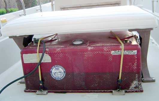 |
Pate Fuel Tank In Red
In addition to off-white hues, the Pate Fuel Tank is also
available in more traditional red. The fuel level in the tank
can be easily seen in this somewhat translucent finish.
PhotoCredit: Christopher Hendrix |
The following is some research based on forum members' contributions
(cited without attribution).
An alternative
method of installing a Pate C27 tank that does
not involve as much alteration of the boat was suggested in a follow-up
posting. This may work on your Montauk depending on the exact
arrangement of the components like the Reversible Pilot Seat, the
hawsepipe and the tank mats. [jimh-August, 2002]
A comprehensive thread on Montauk fuel tanks is
in the Repair/Mods Forum. It contains a great
deal of information on this subject and should be consulted by
anyone interested in on-deck tanks.
Coast Guard regulations define "portable" fuel tanks as less than 7 gallons
capacity. [This is in dispute. The actual regulations do not appear
to cite any particular capacity, but rely on the ability of the persons
onboard to be able to move the tank as a verification that the
tank is not a "permanent installation." The Coast Guard Auxiliary vessel safety inspection form appears to define a portable tank as less than 7-gallons--jimh]
Any "permanent installation" fuel tank must have a vent which is plumbed overboard. In theory, any tank on board your boat without an overboard vent which you could not demonstrate could be lifted and removed would fail a Courtesy Safety Inspection (done by the Coast Guard Auxiliary). Most boat and engine manufacturers don't sell their boats with the larger portable
tanks, thus avoiding the issue. The tank manufacturers (Tempo, Moeller, and others), are selling a tank-only and are not responsible for how you use it, and they sidestep the issue in that fashion.
The most common tank in a Montauk was a 12-gallon tank with mechanical gauge
with rough dimensions of 12 x 14 x 18.5 inches.
Stainless steel tanks are the most likely to develop leaks.
The risk of static electricity explosion is greater in plastic tanks
as they are not easily grounded and rarely grounded properly.
Big Single Tank vs. Twin 12-gallon Tanks
With twins you have the ability to adjust the balance of a Montauk
with the fuel load, (we all know how important it is the adjust weight
to get a Montauk to run on an even keel).
You can also run the fuel hose for your main motor off one tank and
the fuel line for the kicker off the other. When fuel gets low, but not
empty, on the main engine's tank, you just swap hoses.
It is also a lot easier to slide a full 12-gallon tank back under the RPS
than it is with the big tanks which always seem to have some gas cap conflict
or chocking issue.
Mirax Brand Tanks
UPDATE 2011—Mirax Fuel Products is the new name for the manufacturer of Mirax aluminum fuel tanks.
[See updated information above on Mirax. This older information is no longer accurate--jimh] Mirax are still making aluminum tanks for Boston Whalers. The company is Mirax Chemical Products in St. Louis, MO, (Phone number is (314) 752-1500) and they have a sister company KSH Marine.
For a Montauk's under-the-RPS a 12 gallon aluminum tank complete
with cap and dip tube is available for roughly $175. You'll want two.
If you want to run a single tank, you can save a few bucks:
a 24-gallon tank is about $265. They offer a lifetime warranty to the
original purchaser. I believe they would work with you if you want to have a
tank of a different size to put in a different location.
Todd Brand Tanks
Todd Enterprises [at one time made] a number of tanks,
and one of them was claimed to be "Factory designed for Boston Whaler applications." It is an 11-gallon red cross-linked molded polyethylene tank.
Tempo Brand Tanks
Tempo Products [used to] make a variety of fuel tanks. [Tempo Products stopped manufacture of fuel tanks in c.2007. They no longer have even a website presence.--jimh]
The Tempo 28-gallon tank claims to fit perfectly under the seat. Some
have had to replace the filler cap with a low profile cap to make it
fit. Another popular solution is two 13-gallon Tempo's. Unfortunately, all
of the Tempo tanks are red plastic.
The Tempo #C2814 28 gallon tank will fit under the seat perfectly but you do
need to slide it aft for filling. The mechanical gauge on the 28 gallon is
inaccurate. Tank is $105 bought right. Hold down kit is about $15.
Anecdotal reports cite Tempo tanks leaking
through the "fuel gauge" fittings from day one.
The 12-gallon Tempo tanks would not fit under the seat because of the high
vent/fuel cap. Replace with a low profile vented cap; slide them out for
fuel.
The Tempo 19-gallon tank the part number is F1218. Dimensions (in inches)
are 15 W X 28 Lx 12 3/8 H.
Moeller Brand Tanks
The Moeller tank model number 31620, 20-gallon capacity, measures about 28-inches wide by 15-inches deep by 12-1/2-inches high and fits under a Reversible Pilot Seat. You can still use the original hose opening in the floor of the Montauk. [Also see Moeller's website for for information on Moller on-deck or topside fuel tanks and portable fuel tanks. Also see a good discussion in THE GAM about the recent introduction by MOELLER of a 24-gallon on-deck fuel tank in white that is specifically designed for use with the Boston Whaler MONTAUK-jimh.]
Further Reading
Here are some of the excellent forum threads on On-deck Fuel Tanks,
which are the source of much of the information presented above:
DISCLAIMER: This information is believed to be accurate but there is no
guarantee. We do our best!
The page has been accessed times.
Copyright © 2002 by Robert Schmidt and James W. Hebert. Unauthorized reproduction prohibited!
This is a verified HTML 4.0 document served to you from continuousWave
URI: http://continuouswave.com
Last modified:
Author: Robert Schmidt with an introduction byJames W. Hebert. Conversion to HTML by James W. Hebert.
This article first appeared June 9, 2002.
Edited some material related to USCG Regulations on tanks, August 23, 2002.
Appended links to other threads November, 2003.