
by Bob Kurtz
My 2003 Boston Whaler 160 Dauntless came from the factory with Teleflex No Feedback cable steering with a tilt-helm. This system prevents the wheel from turning due to engine forces; the wheel simply stays wherever you put it. Although it had an odd dead spot when first turning the wheel until the clutch engaged, it was easy to get used to and quite effective.
After about eight years, I found that the cable would seize up in the engine steering tube over the winter. It wasn't possible to free it up through steering wheel pressure, but a few hits with a rubber mallet on the end of the steering rod usually did the trick. However, by about year ten, it became very hard to free up and started to seize up even when left alone for just a week or two. It was time either for a steersman nut or for an upgrade to hydraulic steering, and I chose the upgrade to a BayStar steering system. This article provides instructions for this upgrade.
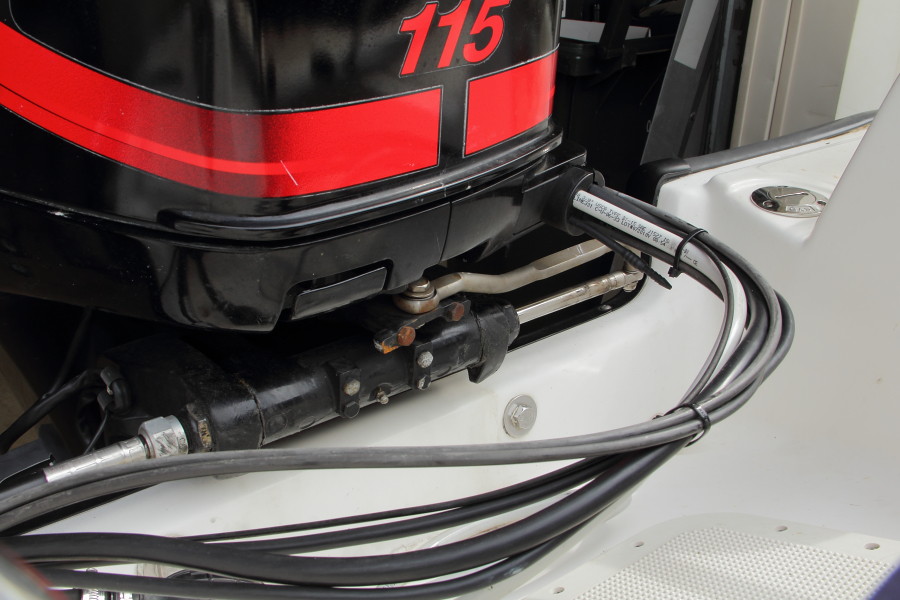
Fig. 1. The steering cable enters the tilt tube from the starboard side (left in this photo) and would would seize up in the off-season.
The first step is to remove the steering wheel. After removing the center cap and retaining bolt, use a wheel-puller to separate the the steering wheel from the steering shaft.
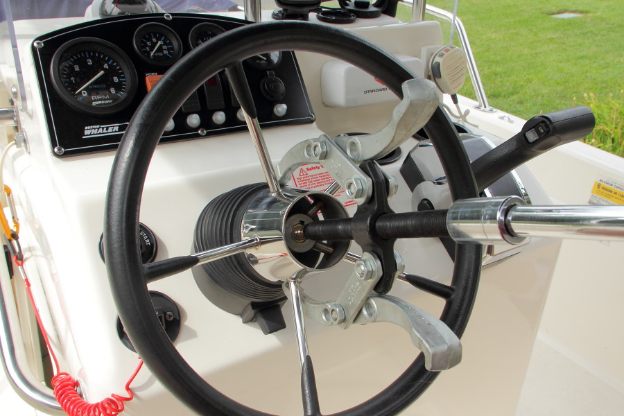
Fig. 2. Use a wheel puller to separate the steering wheel from the steering shaft.
With the steering wheel off, remove the rubber accordian gasket and plastic base. Remove the machine screws on either side of the tilt-helm.

Fig. 3. Remove the rubber and plastic trim to expose the tilt-helm unit.
The Teleflex tilt-helm has a hidden Allen bolt that couples the tilt shaft to the fixed shaft. Remove the Allen bolt and then remove the tilt-helm unit.
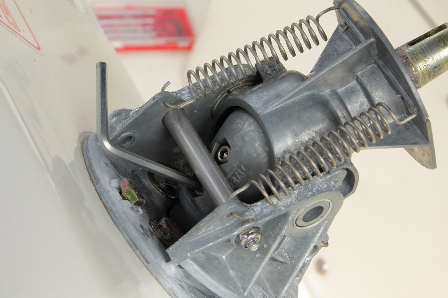
Fig. 4. A hidden Allen bolt connects the tilt-helm to the fixed steering shaft.
Remove the three inner bolts that connect the steering gearbox to the mounting plate and separate the gearbox from the plate. Remove the three outer bolts and remove the mounting plate from the console.
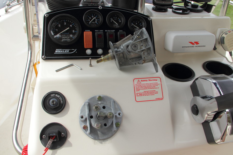
Fig. 5. Remove the three inner bolts to separate the steering gearbox.
At the engine, remove the steering link that connects the engine to the steering shaft.
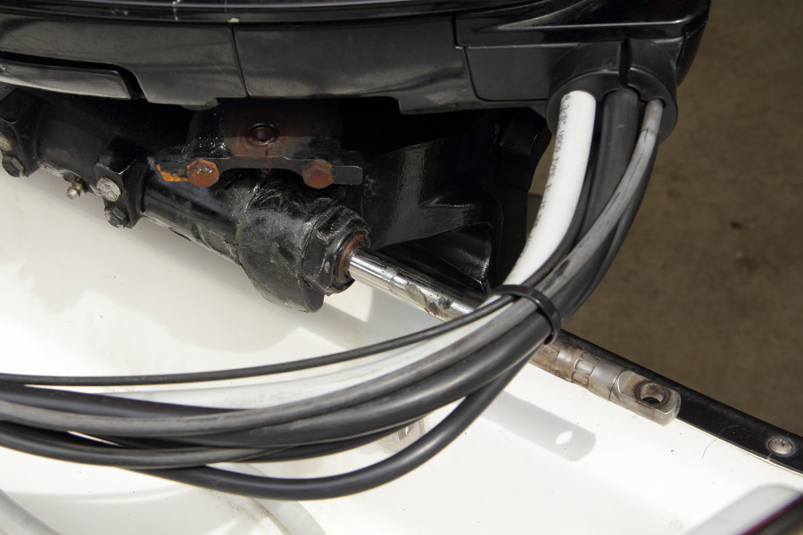
Fig. 6. Remove the steering link.
Most of the engine weight is borne by the tilt tube, so support the engine thoroughly before proceeding. In my case, I backed the boat partly into the garage and supported it from the top with tie-down straps while also supporting it from the bottom with a block under the skeg.
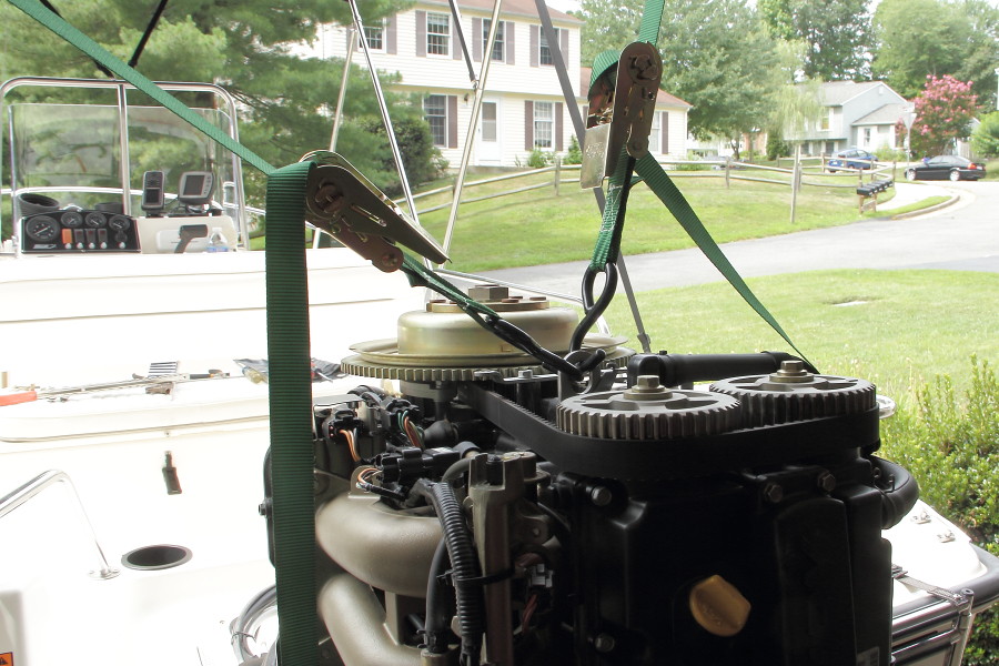
Fig. 7. Support the engine carefully.
Remove the bolt on the starboard side of the tilt tube that holds the steering cable to the engine. Carefully remove the steering shaft from the tilt tube. Mine was very stiff, and I had to bang it out from the other side using a long 3/8-inch socket extension. On the 160 Dauntless, it helps to remove the sleeve that covers the steering and engine control cables where they come out of the hull; that give a much-needed extra quarter-inch of clearance.
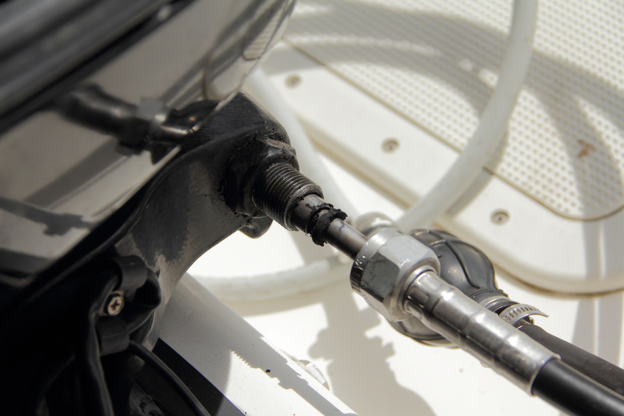
Fig. 8. Disconnect the steering cable from the engine and remove the steering shaft from the tilt tube.
Remove the steering cable from the boat. Before pulling the cable through the under-deck rigging tunnel, attach a cord to allow you to pull the hydraulic hoses through later. Clean up the front and back sides of the console in preparation for mounting the new helm.
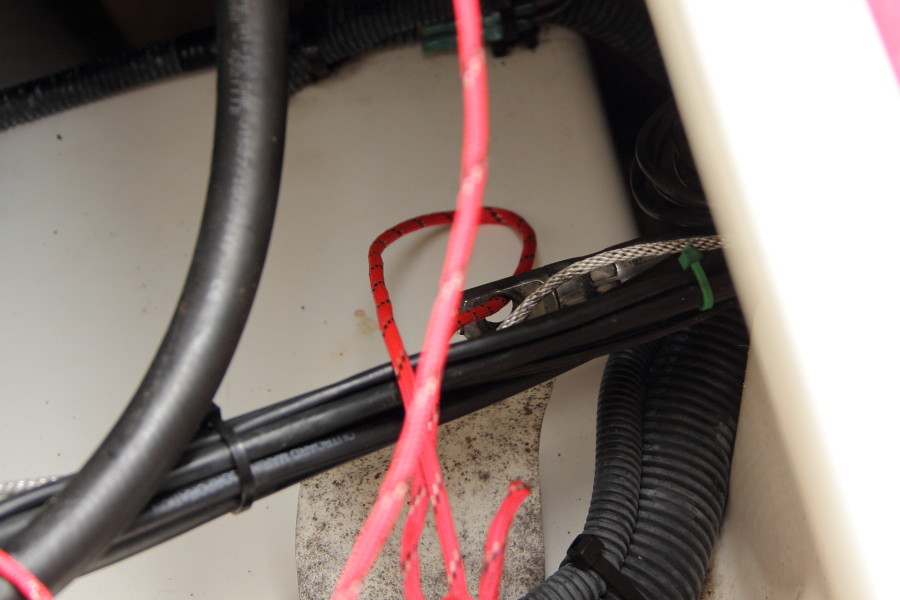
Fig. 9. Remove the steering cable from the boat, pulling a cord through the rigging tunnel for later.
Unpack the BayStar steering kit. This kit, #1-HK4200-T, included everything that's needed: the new helm pump, a new tilt-helm mechanism, the engine cylinder, 20' hydraulic hoses, and hydraulic fluid. Note that the new hydraulic tilt-helm is slightly different than the old cable one, so if you want to retain the tilt capability you must order a tilt-helm with the BayStar system.
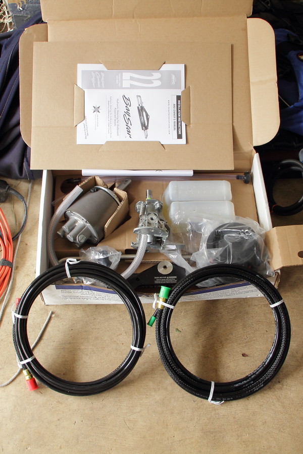
Fig. 10. The BayStar steering kit comes with everything that's needed for the job.
Install the threaded elbow fittings on the BayStar helm pump, with the fittings facing the direction that the hoses will be rigged when the hydraulic fluid fill port is facing up. Bed the fittings in teflon compound. Do not use teflon plumbers tape, since bits of the tape can get into the system and damage the pump.
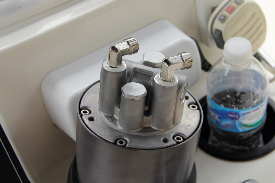
Fig. 11. Install the elbow fittings using teflon compound.
Bolt the new mounting plate to the console, then fix the helm pump to the mounting plate. Be sure that the hydraulic fill port is facing up.
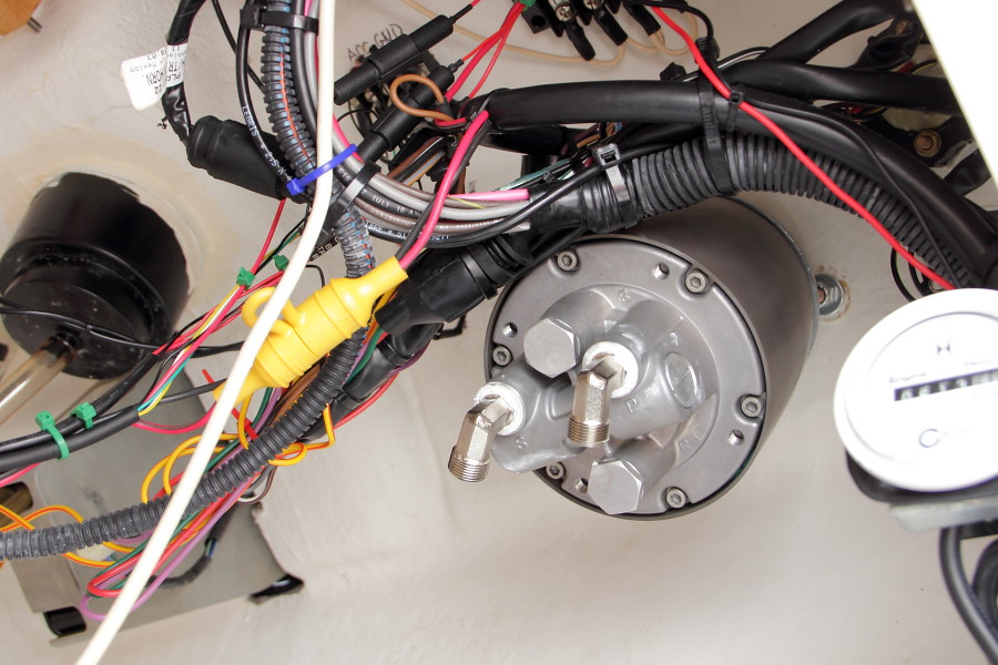
Fig. 12. Install the new mounting plate and connect the helm pump.
Connect the tilt-helm to the front side of the mounting plate, then install the rubber and plastic mounting material over the tilt-helm and mount the steering wheel.
Lubricate the L-shaped steering arms for the engine cylinder and insert them into the tilt tube, then loosely add the retaining nuts on each side of the tilt tube. Connect the steering arms to the ends of the steering cylinder, then mount the steering cylinder onto the engine.
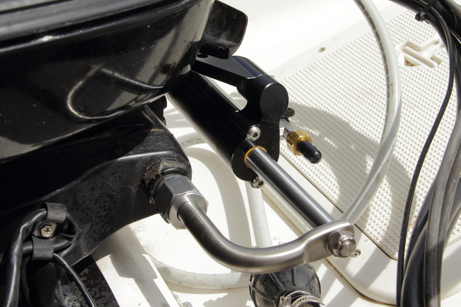
Fig. 13. Install the steering cylinder onto the engine.
Using the messenger cord from earlier, pull the unfinished ends of the hydraulic hoses from the center console through the rigging tube. Be sure the hoses are firmly tied to the cord so it doesn't all come apart inside the hull. Bring the hoses out to the engine, but don't attach them yet.
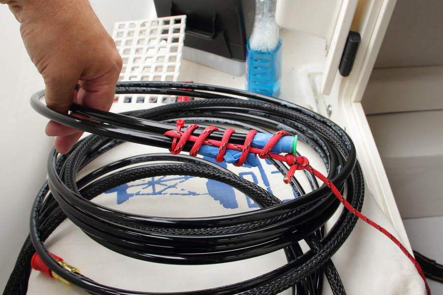
Fig. 14. Pull the hydraulic hoses through the rigging tunnel.
Attach the hydraulic hoses to the helm pump, again using teflon compound on the threads. Make sure there's a nice fair run to the rigging tunnel with no kinks in the hoses.
Fig. 15. Attach the hydraulic hoses to the helm pump.
At the engine, arrange the hydraulic hoses so that they go past their connecting points and make a 180-degree turn before attaching to the steering cylinder. Cut the hydraulic hoses to the desired length and attach them to the steering cylinder. Connect the fill hose to the helm pump. It is easiest to do this by removing the compass and filling the helm pump from above the console.
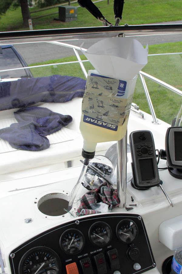
Fig. 16. Attach the fill hose to the helm pump through the compass mounting hole. Here I've cut off the bottom of one of the hydraulic fluid containers and fixed it to the console rail with duct tape to make refilling easier. Note that I'm also using a paint filter to keep any dirt out of the helm pump.
Attach a bleed hose to one side of the steering cylinder and open the bleed valve. The BayStar manual has very complete instructions on how to perform the bleeding process, but here is a summarized version. Turn the steering wheel in the proper direction to pump hydraulic fluid through the hoses and cylinder and into a clean collection container. Frequently pour the collected fluid back into the helm pump supply; if the helm pump ingests air then the bleeding process must start all over again. Periodically switch to the other bleed valve (turning the wheel the other way).
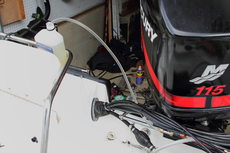
Fig. 17. Bleed the hydraulic system.
Continue bleeding the system until the hydraulic fluid no longer contains bubbles. It takes a long, long time to get all the air out of the system. The hydraulic fluid will contain tiny bubbles for quite some time. Be sure to allow the collected fluid to settle so that all the bubbles separate before pouring the fluid back into the helm pump supply. Expect to do this 20-30 times until the fluid is completely free of air.
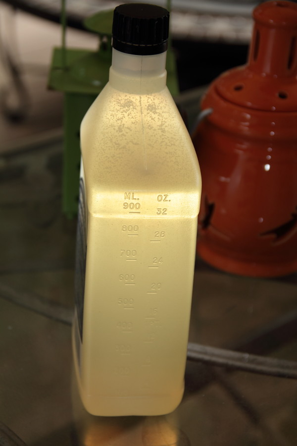
Fig. 18. Allow the tiny bubbles to separate out of the hydraulic fluid before reusing for the helm pump supply.
When the fluid runs clear, close the bleed valves and turn the wheel stop-to-stop several times, then bleed the system again. Repeat until no more air can be seen in the hydraulic fluid. Do one final bleed to empty the helm pump supply container, then remove it and cap the hydraulic fill line. BayStar provides a fill fitting that can be installed on top of the console, but I did not use it. Tighten all hydraulic fittings and add the rubber caps on the steering cylinder bleed valves.
Now you're ready to go! Compared to the cable steering, the hydraulic system is an absolute joy to use. It is silky-smooth and very sensitive to small inputs, with no dead zone. It really is a very nice upgrade.
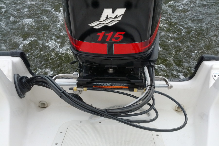
Fig. 19. The steering upgrade is all done, let's go boating!

