search | FAQ |
profile | register | author help
|
|
|
| Author | Topic: E-TEC GEN 2 Rigging Center, ICON II Controls |
| jimh |
 posted 06-25-2014 09:14 AM ET (US)
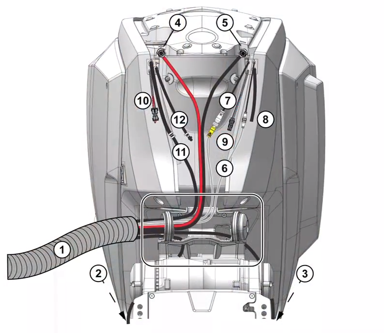
 E-TEC GEN 2 Rigging Center, ICON II Remote Controls RIGGING CENTER All battery cables, network bus cables, hydraulic steering hoses, fuel and oil hoses, and related rigging for the engine enter the rigging center through a cable entryway via a large diameter rigging hose. Optional cables including the Auxiliary Battery Charging cable, a remote oil tank hose, and a remote flush hose can also be routed via the rigging hose.
As shown in the diagram: ICON II ENGINE CONTROL NETWORK At the helm, ICON II rigging will consists of |
| jimh |
posted 06-30-2014 01:52 PM ET (US)
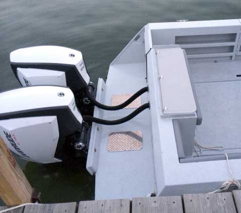
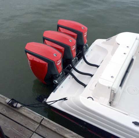
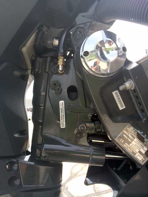
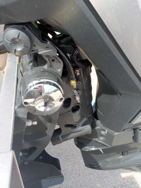
Here are several views of the rigging of the new E-TEC G2 engines on various boat transoms.
|
| jimh |
posted 06-30-2014 03:34 PM ET (US)
In the above images it appears that there are no mechanical tie-bar linkages between the engines. Since there does not seem to be a tiller arm extension on the E-TEC G2 engine, it may be that there are no provisions for installing a mechanical tie-bar to link the engines. This suggests that twin engine or other multiple engine installations can all be adapted without much modification to independently controlled steering for each engine, which can then be controlled by a joy stick controller to give a very new kind of differential thrust steering and control for low speed maneuvering. E-TEC has already had independent hydraulic steering with joystick control in their Optimus 360 steering system. The Evinrude Optimus 360 used the ICON engine controls to manage throttle and shift, and external power steering pumps to manage the engine steering. This same approach seems to now be possible via the ICON II engine control network and the new E-TEC G2 engine mounting/steering/trim-tilt assembly. So joystick steering for twin engines should not be too far away in any E-TEC G2 installation, it would seem. A further integration of the built-in power steering would be with auto-pilots. I am looking forward to hearing more about auto-pilot use with the E-TEC G2. I bet we will see some announcements on this in the near future. |
| djahncke |
posted 06-30-2014 10:45 PM ET (US)
Joystick steering with E-TEC G2 engines is available with the launch of the G2's. I rode on a pontoon boat in Milwaukee with twin 300-HP E-TEC G2's and joystick control. It behaved like my Optimus 360 installation only quieter and smoother with the electric shift. |
| jimh |
posted 07-01-2014 07:50 AM ET (US)
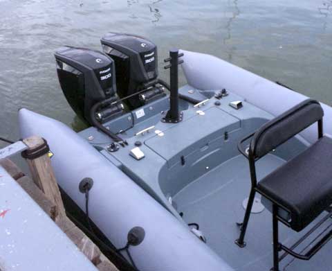
Below is a twin-engine installation on an inflatable boat. It must be a rather rugged inflatable to handle 400-HP--or is that 600-HP?
|
| jimh |
posted 07-01-2014 07:59 AM ET (US)
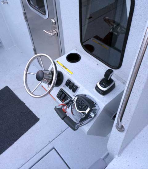
Another E-TEC G2 installation shown below has a second station in the cockpit of a cabin boat.
|
| Hoosier |
posted 07-01-2014 11:05 AM ET (US)
The accidental sequence of these two threads got me thinking, when there are three engines, how is the prop rotation usually set up? Which way does the center engine go? |
| Dave Sutton |
posted 07-01-2014 01:06 PM ET (US)
Jim, the inflatable (RIB actually) I photographed was a military/police specification Zodiac demo boat. I'd guess it at about 20 feet. One interesting thing was that the triple powered Topaz only had two throttles. Obviously there's logic of some sort in the system for slow versus high speed control. My guess is that when differential power is used (reverse on one and forward on the other for dockside maneuvering) the center engine stays at idle, centered, and neutral. Differential steering is obviously available thru the joystick control. Dave . |
| jimh |
posted 07-01-2014 02:34 PM ET (US)
ASIDE to DAVE on new topic of multi-engine and propeller rotation: If the transom needs 20-inch engines for the outer engines, they are usually set up as the standard rotation, as there is typically no counter-rotation gear case for a 20-inch engine. That puts the counter-rotation engines in the center, where the transom height will be 25-inches and you can get a counter-rotation engine. |
| jimh |
posted 07-01-2014 02:37 PM ET (US)
The ICON electronic controls, and I assume the ICON II will be the same, have only two-lever throttles. See http://continuouswave.com/whaler/reference/electronicControls.html There will be separate trim switches for three, four, and five engine installations. The action of the two throttle levers must be programmed in some manner to control the three, four, or five engine configurations. I don't recall precisely what the protocol might be, but, as proposed, the middle engine or engines may be left in neutral if the throttle levers are split to mixed forward and aft propulsion. |
Powered by: Ultimate Bulletin Board, Freeware Version 2000
Purchase our Licensed Version- which adds many more features!
© Infopop Corporation (formerly Madrona Park, Inc.), 1998 - 2000.