continuousWave --> Whaler --> Cetacea
Previous | Next

[Logo: WHALER CETACEA]

Cetacea Page 56

April 9, 2002

Whaler Repowering

Repowering the earliest Boston Whaler hulls has become a challenge in recent years due to their transom height. The 13-foot boats had rather short, 15-inch transoms. Most modern engines in the 30-50 horsepower range are made only in 20-inch shaft versions. To some extent this same problem is repeated on some older hulls with 20-inch transoms. Often motors of a certain horsepower or engine type are made only in 25-inch shaft versions. Again, there is a height mis-match. Mounting one of these taller engines on an older Whaler requires some adaptation. Here is one solution.

That Elusive Smell of Forty Year Old Wood

Carl Neusel of the San Francisco Bay area of California, repowered his 1962 Boston Whaler 13-Sport with a 2002 Mercury 40-HP 4-stroke engine with a 20-inch shaft. Here is Carl's narrative of how he overcame the problem of mounting the tall engine on the short transom, along with many detailed photographs of his excellent installation:

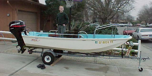
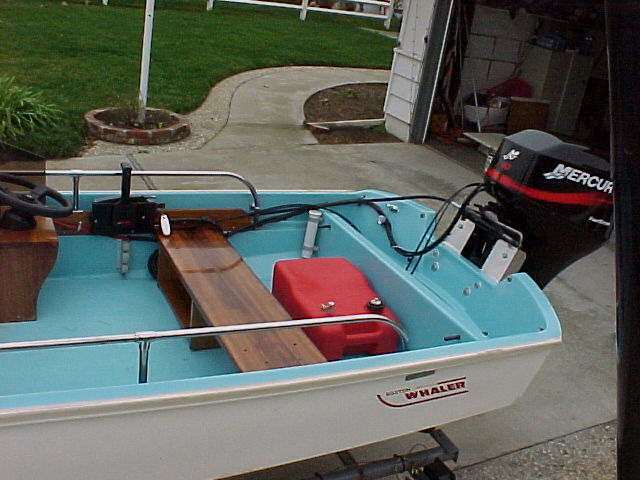
"I acquired the boat, hull number 5620, in the spring of 2001. The previous owner had always used clamp-on outboard motors so the transom had never been drilled. 
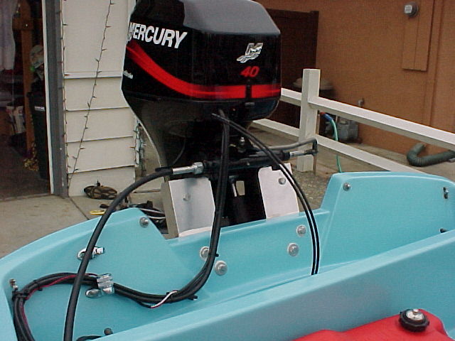
After comparing various outboard motors in the 25-40 HP range, I decided on a Mercury 40-HP 4-stroke. I chose a 20-inch shaft model for several reasons. First, it had a power trim and tilt option that I thought would aid in operating the motor given its 212 pound weight. Second, it would make upgrading the steering from the original rope/pulley to Teleflex a snap. Finally, if something were to happen to the boat, the 20-inch shaft motor would hold more value compared to 15-inch shaft.

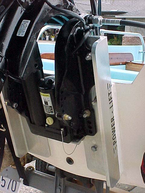
"I purchased a set of CMC Vertical Extensions to raise the motor. These jackplates were quite sturdy, had plenty of drilled holes to accommodate standard bolt patterns, and created a minimum of set-back. By using separate plates, I could also ensure that the bottom of the plates would not block the drain on the outer hull.

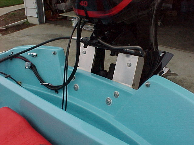
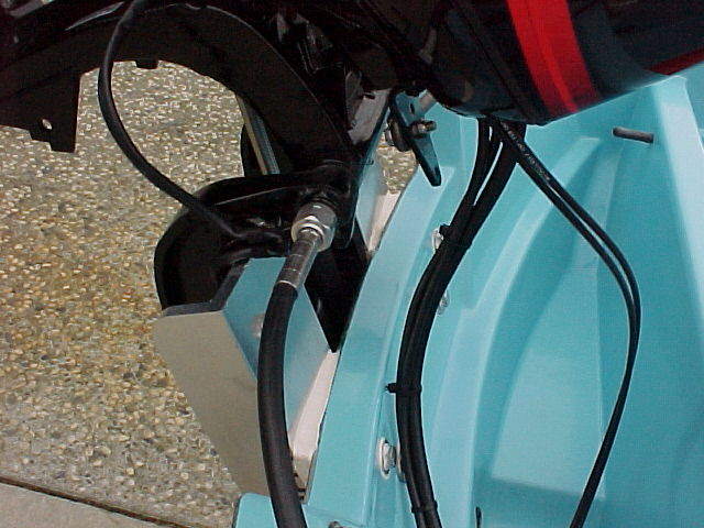
"The problem I faced when installing the motor was how to fit the flat surfaces of the jackplates to the 13-footer's curved transom. I did not want to place a bending force on the cast aluminum outboard mounting bracket, nor did I want to use washers as shims. I decided to create a pair of shims from 1/8th-inch thick plexiglass sheets. The shims would measure the length of the jackplates and would decrease in taper in width inward toward the center of the transom. I used 1/8th-inch plexiglass because the finished shim could be flexed a little to form to the transom and I could create a smoother taper.

"Using 1-inch plywood, I made a template of the outboard mounting bracket, complete with bolt pattern holes. I clamped the template to the outside of the transom and was able to determine the thickness and degree of taper for the shims. Next, I cut the plexiglass sheets into strips to fit the dimensions of the jackplate surface minus 1/4-inch on all sides. I wanted a "gutter" in which I could put ample quantities of 3M-5200 sealant to seal the outer edges of the shims and have even finished surfaces. I cut more plexiglass into strips of decreasing width and epoxied the strips together to form a shim. Again using the plywood template, I drilled bolt holes into each shim.

"Finally, it was time to drill the transom!

"I held my breath after re-measuring and re-checking the placement of my plywood template, and drilled four holes. After nearly forty years, the wood was dry and solid (it even smelled good). I doubled up on the upper holes so I would have four solid through-bolted attachment points.

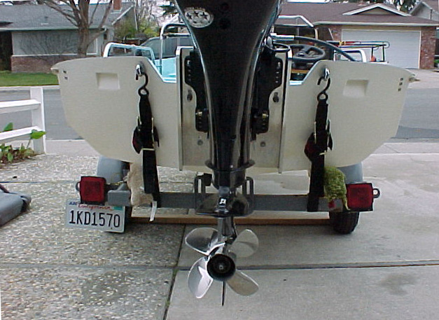
"I applied copious amounts of 5200 to all the mating surfaces and installed the jackplates to the transom. 
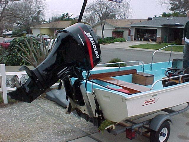
With the help of two adults and a come-a-long, I hoisted the outboard, positioned it onto the jackplates, then bolted it all together.

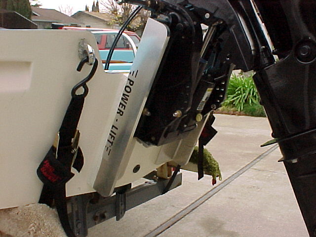
"With some reluctance I used lag screws to attach the bottom of the jackplates to the transom. I would have preferred to through-bolt the bottom holes, but could not find a practical way of doing it without cutting large holes in the bottom of the transom which would have to fiberglassed over. 
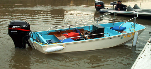
After a lot of trailering, reversing the outboard and a summer of use, I have yet to encounter any loosening of the lag screws or any other part of the installation. When trailering the boat, I use a outboard support lever.

"Before embarking on this installation, I read nearly every pertinent post in the Classic Whaler Forum archives. Simply put, I could not have done this without the advice and knowledge I received through the Reference section and Forum contributors. 
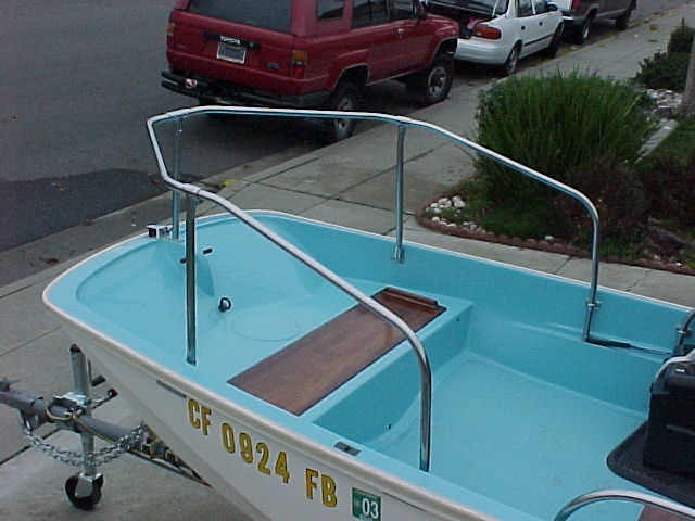
I love Classic Whalers and have loved them since I was a young teen. Something about the blue interior and the hull design quickens my pulse. In my opinion jimh has created the finest resource and historical record in existence on these beautiful boats. Thanks."


Photo: 1962 13-Sport on trailer; young boy standing in cockpit; new Mercury 40-HP on transom.
1962 Whaler Repowered and Reborn
This 40-year-old Whaler looks like new, and thanks to a new 40-HP Mercury outboard it will run like new. Before getting to the details of the engine mount, I have to observe that just as Boston Whaler often did in their advertising photography for these diminuitive 13-foot boats, Carl has included his young son in the frame to lend a very favorable sense of scale. From the way this boat looks now, that young man will still be enjoying it 40 years from now.
PhotoCredit: Carl Neusel - Reference: 56-01


Photo: 1962 13-Sport on trailer; close up of engine mount and bracket from rear
1962 Boat Meets 2002 Motor: Bolt Problems
Adapting a 20-inch shaft engine to a 15-inch high transom, Carl used a two-piece aluminum jackplate to provide the proper engine mounting height. The early Whaler engine well has always been a problem for the lower mounting bolts of modern engines. The bottom bolt cannot be through bolted, but instead a lag screw is used to secure the bracket to wood imbedded in the fiberglass hull.
PhotoCredit: Carl Neusel - Reference: 56-02


Photo: 1962 13-Sport on trailer; close up of curved transom meeting flat bracket
Straight meets Curved
Adding more complications, the face of the Whaler transom is curved while the bracket is flat. Note the additional of shims (hidden under the sealant) to flatten out the curve of the transom face.
PhotoCredit: Carl Neusel - Reference: 56-03


Photo: 1962 13-Sport on trailer; view of engine mounting from cockpit side
Double Bolted
Since the upper bolts carry most of the loading, Carl doubled up on them. That blue gelcoat looks great!
PhotoCredit: Carl Neusel - Reference: 56-04


Photo: 1962 13-Sport on trailer; view of cable steering and other control cables
Cable Steering
The original Whaler used wire rope and sheeve blocks for steering. Carl upgraded to TELEFLEX cable steering. The raised mounting helps avoid problems with clearance for the cable and the drag link. When mounting 15-inch motors on the transom it can be a challenge to get the cable steering installed.
PhotoCredit: Carl Neusel - Reference: 56-05


Photo: 1962 13-Sport on trailer; stern quarter view
Full Tilt
With the raised transom mounting, the engine lower unit will easily clear the water when tilted to the full-up position. Hydraulic power tilt and trim made moving the over 200-pound engine much easier.
PhotoCredit: Carl Neusel - Reference: 56-06


Photo: 1962 13-Sport on trailer; close up of jackplate area from overhead
Well Sealed
Use plenty of sealant when installing the through bolts and jackplate. The last thing you want is water entering the hull interior space.
PhotoCredit: Carl Neusel - Reference: 56-07


Photo: 1962 13-Sport on trailer; view of bow with OEM railing
Bow Rail Option
This boat has the tall bow railing option. If you look just behind the lifting eye in the bow you can see the circular fiberglass and gelcoat plate that covers the sprue hole used in the foam filling operation.
PhotoCredit: Carl Neusel - Reference: 56-08


Photo: 1962 13-Sport on trailer; view of rear half of cockpit
Whaler Wood
In addition to the repowering, the rest of the boat is in factory-new condition. The mahogany thwart, risers, and console look great. A very neat job has been done with the control cables and wiring.
PhotoCredit: Carl Neusel - Reference: 56-09


Photo: 1962 13-Sport on trailer; view of 4-blade stainless steel propeller
Trophy Prop
After all the other renovations, you can't skimp on the propeller. I bet that 4-blade stainless steel prop cost more than the hull did in 1958!.
PhotoCredit: Carl Neusel - Reference: 56-10


Photo: 1962 13-Sport in water showing static trim with modern 4-stroke engine
Static Trim
The 212-pounds of the modern 4-stroke is probably more weight on the transom than the designers of the original Boston Whaler imagined would be used, but the boat carries the extra weight quite well.
PhotoCredit: Carl Neusel - Reference: 56-11


continuousWave --> Whaler --> Cetacea
Previous | Next

DISCLAIMER: This information is believed to be accurate but there is no guarantee. We do our best!

The page has been accessed 63885 times.

Copyright © 2002 by James W. Hebert. Unauthorized reproduction prohibited!

This is a verified HTML 4.0 document served to you from continuousWave
URI: http://continuouswave.com/whaler/cetacea/cetaceaPage56.html
This article first appeared April 10, 2002.
Last modified: Sunday, 01-Jun-2003 14:56:39 EDT
Author: James W. Hebert