Drilling new mounting holes.
Because of the construction of the transom of the Boston Whaler 170 MONTAUK, special consideration must be given to mounting an auxiliary motor directly to the hull in lieu of using an outboard motor bracket. Such an installation is described and shown.
I have installed a Mercury 5-HP four-stroke auxiliary motor directly to the starboard side of the transom of my 2006 Montauk 170. The entire procedure consumed 16 hours of time. The only task left to perform is to restore the gel coat, for which I am awaiting warmer weather to accomplish. It was only due to the very kind and expert assistance of Jim Hebert, that you are able to view the photographs provided herein.
The main tools and supplies needed were:
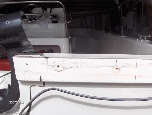
Remove the two visible stainless steel screws retaining the black transom trim molding on the starboard side of the transom notch. Gently lift the black transom trim molding vertically. Be careful; the factory has run beads of black sealant along both top and bottom edges. At this point you will note an embedded bow navigation lamp wire (black/gray insulated conductors) which exits the hull and travels up between the round and flat portions of the rub rail.
Gently pull the round black vinyl insert portion of the rub rail from the rub rail track. The navigation lamp wire will now fall away.
You will now see four stainless steel screw heads counter sunk into the rub rail. These are 1-1/4-inch long. Remove all four. Now gently pull the rub rail toward your until you have removed it to the starboard stern corner of the transom. Tie it off temporarily. Again, be careful since the rail has white caulking binding it to the hull a bit in places.
Climb aboard, open the round inspection cover located below the starboard stern seat, fish out the bow navigation lamp wire, snip off at the connector, and remove via the exit at the stern. This is necessary so as not to damage the wire during the grinding and cutting process.
The Mercury 5-HP four-stroke motors (along with the 4- or 6-HP models) all have identical measurements between the hold-down toggle clamps and the back end of the mount: 2-1/4-inches. This is 5/8-inch narrower than the top of the transom with rail re-moved (2-7/8-inch). In order to allow the kicker to be clamped unto this portion of the transom, it was necessary to cut out 1-inch from the aft portion of the fiberglass at the transom hull joint. The width of the kicker mounting bracket is 6-7/8-inch, and to this I added an additional 1/8-inch for a total cut out width of 7-inches.
Next, following careful measuring to position the kicker accurately and so as not to damage or interfere in any way the Hull Identification Number (HIN), I calculated that 3-inches outboard from the existing transom notch was the best starting point mark. From there I measured a 7-inch width. Then 1-inch inward from the aft edge of the hull joint for the depth of the cut. The cutout depth and width now being 1-inch x 7-inch. The 1-inch depth of cut will make the new notch exactly flush with the rest of the transom.
Using a hacksaw, carefully make the first two end cuts directly on the 7-inch marks to the full depth of 1-inch.
Great care must be taken with the use of the grinder. In other words, don't go for the kill all at once, so to speak, and hold the grinder firmly with both hands so it does not get away on you. Commencing approximately 3/4-inch inside each mark, grind a slot in the hull laminate to a depth of 1/4-inch. Carefully do the same at the underside edge. Continue top and underside until you have cut through the laminate.
Next, use a keyhole saw to complete the cuts and remove the cut-out portion.
Next, with the grinder, sanding disk, and fiberglass file, carefully smooth as necessary until you arrive flush with your cutout markings. You should be left with a hull thickness of l-7/8-inch which is 3/8-inch less then the kicker clamp mount depth.
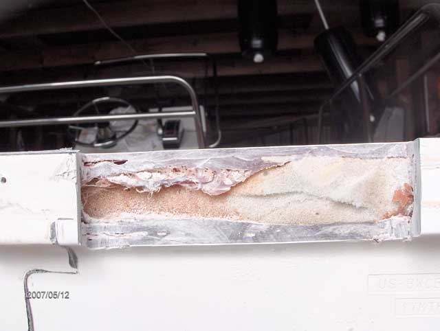
Clean out the sparse bit of foam from within the cutout.
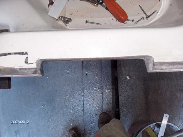
Temporarily re-install the rub rail. Using the hacksaw cut off the rub flush with the outboard end of the new notch. Drill a 5/32-inch pilot hole about 1-inch in from the end of the rub rail. Later, you will insert the leftover 1-1/4-inch screw here in order to draw the rub rail firmly against the hull.
Install the remainder of the rub rail, and holding it in place pre-drill 5/32-inch a pilot hole following the original hole from which you had removed the visible stainless steel screw. Now insert the screw firmly and using the hacksaw cut off the excess piece of rub rail.
Re-install the bow lamp wire along the rub rail below the heads of the stainless steel screws up to the outboard edge of the new notch. Here file a small 1/2-inch crevice into the plastic portion of the rub rail and hull laminate. Place the navigation lamp wire as deep as possible into the cut out from which the foam was removed and out the other side (filing a crevice here again) then down into the hole from whence the wire was removed, re-connecting the wiring later. (Don't forget!)
Firmly re-install the transom trim molding. Now re-install the round rub rail insert which can be done easily gently using a plastic or rubber headed hammer. Cut off the excess piece.
Using duct tape or masking tape, mask the area surrounding where you will be fiberglassing. Using the BONDO or fiberglass resin, fill in that portion where the foam has been re-moved. Make certain the navigation lamp wire stays in deep. Do the glassing in three stages, filing and sanding as you go, so as to end up with a relatively smooth finish, flush with the perpendicular portion of the stern. Remove the duct tape or masking tape.
Next, gently place your auxiliary motor into the cut out. You will note it will not seat properly at the top due to the camber just below the kicker clamps. However, if you pull out slightly on the leg of the kicker while holding the top down it then seats properly but you are now left with an approximate 5/8" gap at the lower back end of the clamp assembly. To solve this problem it will be necessary to remove the small silver-colored cross-member held in place by two countersunk screws and replace with one 5/8-inch in thickness. This I fabricated out of aluminum, to the outside of which I applied a thin rubber covering.
Meanwhile, use an appropriate temporary 5/8-inch spacer, and, being certain the motor is flush on top, tighten the motor clamps down firmly.
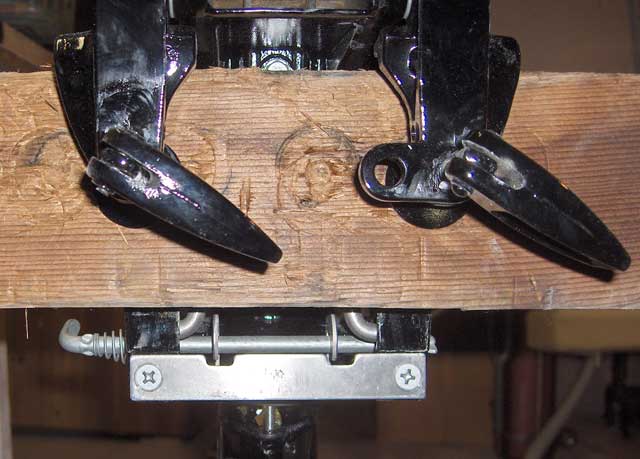
With the kicker now temporarily installed, place a 5/16-inch bit later and increase to 3/8-inch bit that is at least 6-inches in length through the chain hole in the front and below the handle. Angle the bit slightly to your right and proceed to drill, slowly, through the hull. If done properly a 3/8-inch x 4-inch stainless steel bolt with flat washers at both ends and self-locking nut at the back end will clear the round tilt-mechanism. This will secure the kicker against loss overboard, but not for theft! For theft protection you may wish to purchase some type of a locking mechanism that fits over the kicker clamp tightening handles. Remove the kicker.
Drilling new mounting holes.
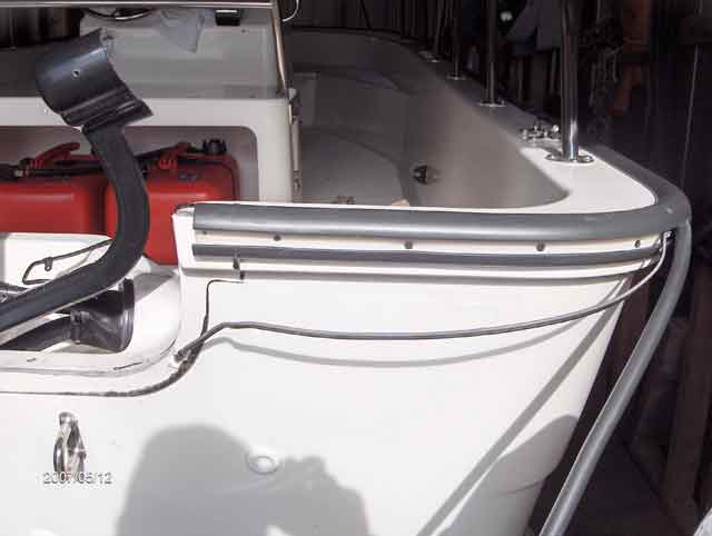
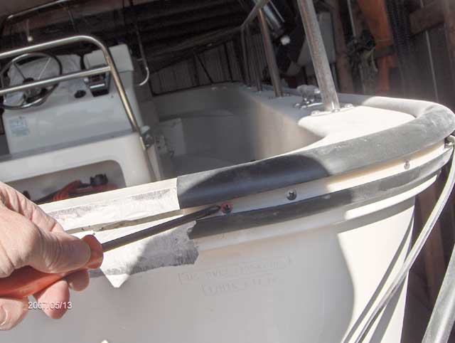
Details of notch, rub rail, and transom trim molding.
Using 3M black sealant, seal the ends of the rub rail and along the top and bottom of the rub rail which had been placed there by Boston Whaler, during the course of construction.
Apply two coats of gel coat finish.
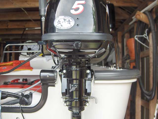
Re-install your auxiliary motor.
Insert the 3/8 x 4-inch stainless steel anchor bolt through the kicker chain hole, liberally coated with 3M white sealant on its shank and exit point prior to affixing the self-locking nut. Do not over tighten the nut, just snug it up.
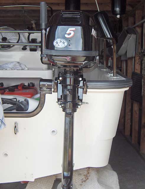
Final Installation.
Since most of this summer will be spent at the cottage and on my 170, I will not have this computer with me in the event you have any questions or wish clarification on any step. Notwithstanding, I do check in periodically and will most certainly reply to any e-mail sent. Good luck to anyone taking on this "Labour of True Love."
The installation was finished after the temperatures warmed up enough to permit use of gel coat resins. A remote throttle was installed on the auxiliary motor, and a mechanical link installed between the two motor tillers to permit combined steering. These details are shown in the photographs below:
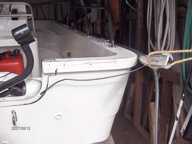
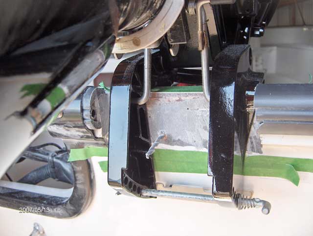
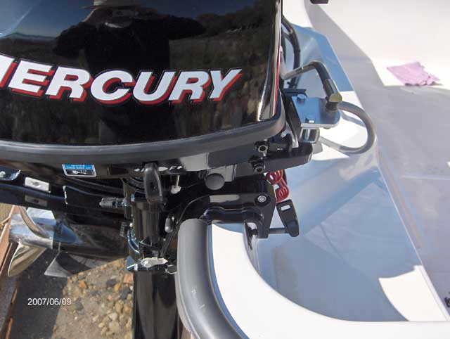
The modified area of the transom under the auxiliary engine mount.
Gel coat finish on transom. The modified hull section is now nicely concealed.
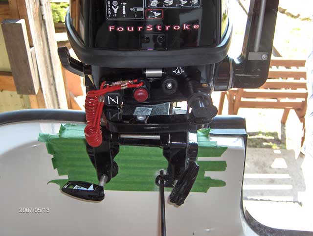
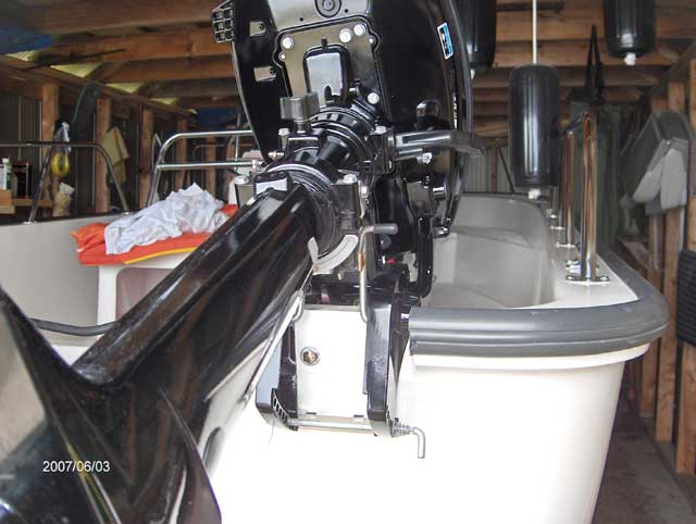
Close up of auxiliary mounting area on transom.
Steering linkage at auxiliary motor. Note rubber pads under motor mounting clamps to prevent maring hull finish.
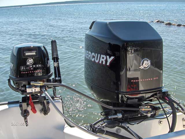
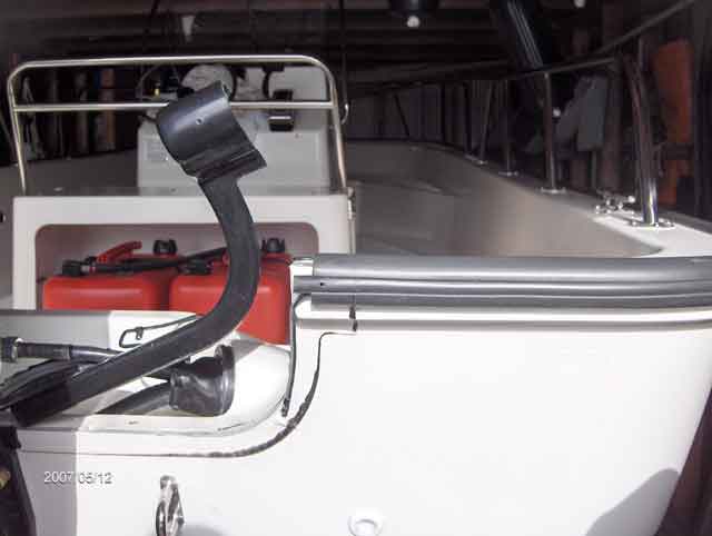
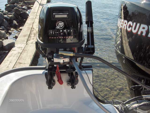
The auxiliary motor is linked to the main motor by this tie bar.
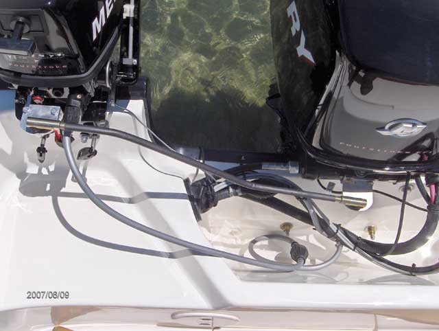
The fuel supply for the auxiliary motor is obtained by a T-fitting on the supply line to the main motor. There has not been a problem with siphoning from the non-running motor.
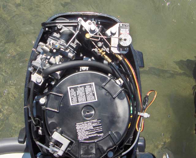
A Trollmaster remote throttle servo is installed on the auxiliary motor to allow control of its speed.
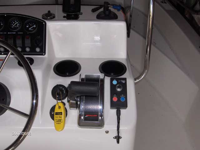
The Trollmaster remote throttle control at the helm.
Questions and comments on this article can be posted to a discussion reserved for that purpose.
DISCLAIMER: This information is believed to be accurate but there is no guarantee. We do our best!
Copyright © 2007 by Ray Dumas. HTML version by James W. Hebert. Unauthorized reproduction prohibited!
This is a verified HTML 4.0 document served to you from continuousWave
URI: http://continuouswave.com
Last modified:
Author: Ray Dumas
This article first appeared May 2007.