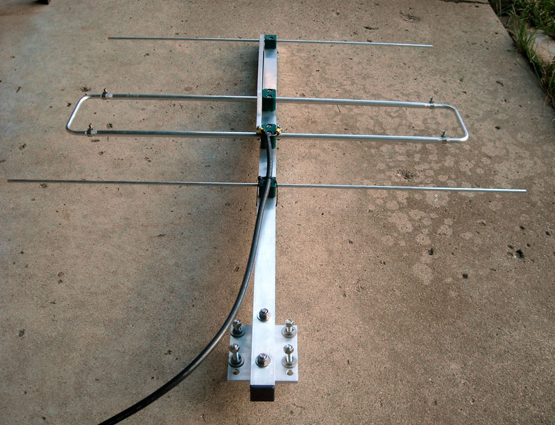
This three-element yagi uses an unusual loop driven element, a method that the designer, Justin, G0̸KSC, calls the Loop Feed Array or LFA Yagi. To the left of the boom is a quarter-wavelength stub that is part of the feed system.
A careful search in made for the optimum directional AIS receive antenna for a shore station. The result is surprising: the antenna is of unusual design, comes from England, is extremely well made, and is an excellent value.
I live about 16-miles from the Detroit River, a busy commercial waterway. Thanks to the International Marine Organization (IMO) mandate for use of Automatic Identification System (AIS) transponders on most large ships, just about every freighter transiting the river is identifying itself with an AIS signal. After an initial test with a less than optimum antenna, I found I could receive AIS transmissions from the area of the Detroit River at my home. I then began a search for an antenna which could be installed on my home's roof to improve the receiver performance. Most antennas made for the VHF Marine Band are omnidirectional vertical arrays. Since the area of interest for reception was from roughly only one quadrant of the compass, a directional antenna would be useful. Directional antennas provide gain in their favored direction, and they also suppress noise and interference in their unfavored directions. Signals from ships are sent with vertical polarization. A small vertically-polarized Yagi-Uda Array (hereafter just Yagi antenna) with a broad main lobe would be a good solution for my location.
The AIS signals are sent on two frequencies near 162-MHz, the upper end of the VHF Marine Band. Most commercially made antennas for the VHF Marine Band are omnidirectional verticals, and their gain is limited. Even to get a modest gain of 3-dB (referenced to a half-wavelength dipole) a rather long antenna is needed (about 8-feet in length). Mounting such an antenna on my roof would also be difficult.
For gain in a compact size, the Yagi antenna cannot be beat. A 3-element Yagi can produce about 6 to 7-dB gain (referenced to a half-wavelength dipole) in a very modest size. (In terms of the usual gain figures associated with marine band antennas--whose gain is usually referenced to an isotropic radiator in free space--a three element Yagi operating over normal ground could have a gain of 9 to 10-dB in marine antenna terminology.) Unfortunately, Yagi antennas tend to be narrow-band antennas, so they must be designed and tuned for the frequency of interest. There were a few commercial-grade small Yagi antennas available, but their cost was objectionable. Due to the limited market application, those antennas are likely not made except on a custom basis, and their prices reflected that. Some suitable AIS-band commercial directional antennas were more than $500. While I would enjoy receiving stronger AIS signals, I would not enjoy it that much.
Below the VHF Marine Band there is an Amateur Radio Service allocation at 144 to 148-MHz, the 2-Meter band. There are dozens of small Yagi antennas made for that band, and their cost is much more modest. Prices for a three-element or four-element Yagi for the 2-meter band ranged from $70 to $115. There was even one small manufacturer making a 160 to 164-MHz version of his 2-meter antenna. That antenna would cost about $80 with shipping for delivery to my location.
Because an antenna tuned for 144 to 148-MHz would have longer elements than needed for a 162-MHz antenna, it would not be difficult to re-tune the antenna for the higher frequency by cutting the elements to shorter lengths. (This is obviously much easier than if one had to add length to every element!) However, getting peak performance from a Yagi antenna requires careful tuning. In fact, most modern antenna design is done using digital computer modeling of the antenna. While a reasonable result can be obtained by simply cutting all element lengths by an amount proportional to the frequency change, there is no guarantee this would give the same results as a careful computer model analysis for the new frequency.
An additional problem with re-tuning a Yagi to 162-MHz from 144-MHz is the adjustment of the matching network. Most of the inexpensive 2-meter band Yagi antennas use a matching network which is very narrow-band, a Gamma-match, and the network would also have to be readjusted to the new operating frequency. This might entail also scaling the dimensions of some of the matching network components. One manufacturer with whom I spoke about this problem cautioned me that adjusting the matching network could be difficult if not at least tedious. The notion of cutting down a 144-MHz antenna to work on 162-MHz was becoming less attractive.
In the process of searching for antennas, I happened to become aware of a small manufacturer in England run by a fellow radio amateur, Justin, G0̸KSC. Justin has developed a new approach to Yagi antenna design, first by using more modern and sophisticated computer modeling software to analyse his designs, and also by employing a loop driven element instead of a simple halfwave split-dipole. Justin cites several advantages to using the loop, including raising the radiation resistance to close to 50-ohms, which allows a direct connection to the 50-ohm coaxial transmission line. This eliminates the need for a matching network, and thereby eliminates the need to adjust the matching network. The loop is also said to have a wider bandwidth than a single dipole element. The closed circuit of the loop is also believed to help reduce noise pick up. In all, the loop feed seems like an innovative idea, which Justin calls the LFA Yagi or Loop Fed Array Yagi. Justin offers a great deal of information on how to homebrew his antenna designs, but he also has a commercial manufacturing operation that will make an LFA Yagi according to his designs.
I emailed Justin to ask what he thought about cutting down one of his designs to move it to 160-MHz instead of 144-MHz. In addition, the antenna would be vertically polarized and be end mounted. Much to my surprise, he replied that he would do a computer analysis of an just such an antenna, and let me know the outcome. A short time later--isn't email wonderful--I heard from Justin with encouraging news. A 3-element LFA Yagi could be made to work well across the whole of the VHF Marine Band. And even more surprising, Justin's company, InnovAntennas, would be pleased to construct one for me, without any additional charge over the standard 2-meter version. Justin explained that all the antennas are built to order, and customizing one for a slight frequency change--or as the British say, "a bespoke design"--would be no more fuss to make than one of their standard Amateur Radio designs.
With this great news I promptly contacted the local distributor in the USA that represents InnovAntennas, R & L Electronics in nearby Hamilton, Ohio, and placed an order. And to my good fortune, I also learned that InnovAntennas was just about to send a shipment to R & L, and my new order could be included. This was great fortune for me.
About two weeks later, including an interlude for the Christmas holidays, I received my InnovAntenna, carefully packed into a heavy-duty shipping tube. As soon as I saw the G0̸KSC antenna in person, I knew I had made the correct choice. This antenna is beautifully constructed. All the machining has been done to a high standard, all the hardware is stainless steel, and all fasteners employ elastic stop nuts. This is an antenna that could easily survive for 20-years in a harsh environment. It is very well designed and very well constructed. The images that follow will give you a good idea of the LFA Yagi antenna's design and construction.
This three-element yagi uses an unusual loop driven element, a method that the designer, Justin, G0̸KSC, calls the Loop Feed Array or LFA Yagi. To the left of the boom is a quarter-wavelength stub that is part of the feed system.
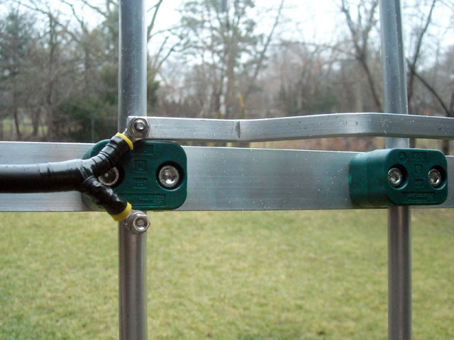
The 0.5-inch-diameter driven element loop, insulated from the boom by the green insulator blocks, allows for a 50-ohm feed point without an impedance matching network. The transmission line (not supplied with the antenna) can be directly connected to the driven element; keep the connections as short as possible.
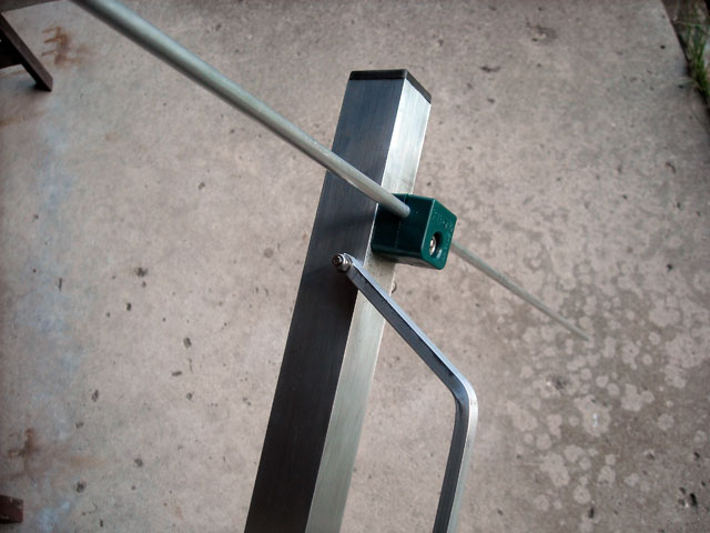
The parasitic elements are made from aluminum rod and are also insulated from the boom. The end of the quarter-wave stub shorts to the boom, acting as a balun for the feed system. All hardware is stainless steel.
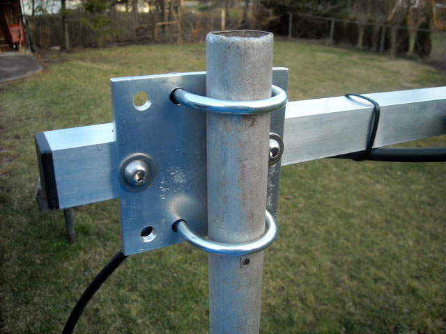
The antenna uses a square boom. A nicely machine aluminum plate provides the boom-to-mast mount. G0̸KSC fabricated the plate for a 2-inch diameter mast. My TV mast is only 1.5-inch, so I had to drill some additional holes and use smaller clamps. This temporary mast is even smaller, only 1.125-inch
To tune the driven element to resonance, I set the antenna on a temporary mast about 8-feet off the ground.
After four test iterations the driven element loop was adjusted for best VSWR at 157.400-MHz, the highest frequency in the VHF Marine Band at which I could transmit with my radio. Stainless steel hose clamps hold the trombone section in place.
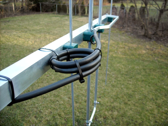
Justin, G0̸KSC, also recommends the transmission line be formed into a two-turn loop to act as a choke-balun to suppress antenna currents on the transmission line. This also helps to keep the pattern free from distortion.
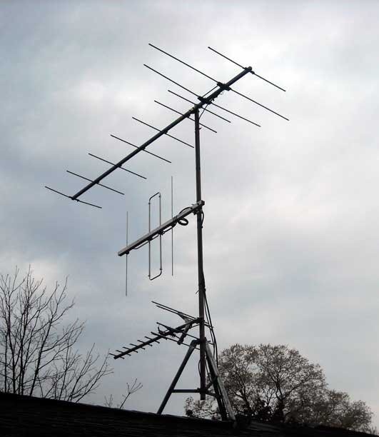
The G0̸KSC antenna on my roof. The upper antenna is a 10-element Yagi for TV VHF Channel-9, which pulls in Canadian station CBET from 29-miles away. The smaller antenna below is for my local UHF-band TV stations, all only a few miles away. The AIS antenna is aligned with the two other antennas to minimize any pattern disturbance.
Once I had assembled the antenna and connected a coaxial feedline, I made an educated guess for the dimensions of the loop driven element, and I checked the VSWR with the antenna held just a few feet above ground and indoors. The transmission line VSWR looked decent. I took advantage of some very mild Winter weather, and installed the antenna on a small mast on my garage roof. This put the G0̸KSC Yagi about 20-feet above ground and aimed at the Detroit River on a true bearing of 152-degrees. The temporary feedline was only long enough to get down from the roof, so I had to set up a temporary receive station outdoors. I sat down to see what ships might be passing by and what their distance might be.
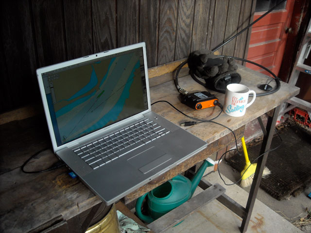
The temporary antenna installation on the roof did not include a feedline long enough to reach indoors, so I had to move my AIS receive station out to the garden.
There is nothing like a good antenna to improve a receiver's performance. I couldn't wait to try the G0̸KSC antenna from my home. Moments after connecting the antenna to my AIS receiver, I had data from seven vessels. The surprise was the signal from the Coast Guard Cutter Mackinaw--my best DX (distance) so far at 32-miles away.
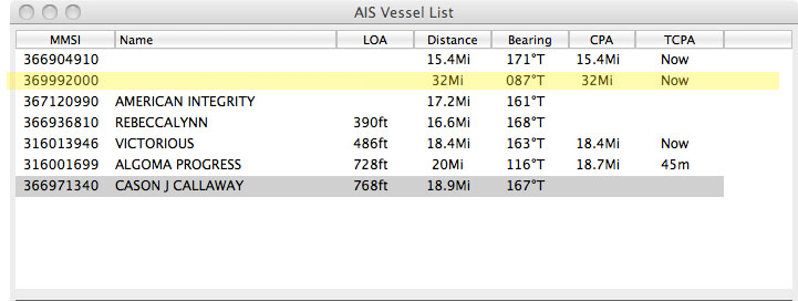
Signals received in the initial test included data from a ship (highlighted in yellow) 32-miles away and 65-degrees off the main lobe of the antena. I considered this good performance.
The USCGC MACKINAW, MMSI 369992000, was heard at a range of 32-miles and a bearing of 087° True. The antenna was oriented on a heading of 152° True, which means the MACKINAW was 65° off-axis. I suspect that a polar plot of the antenna's field would show that at 65° off-axis the response is down in gain and perhaps close to unity gain. A range of 32-miles is quite good, and exceeds my expectations, considering the intervening urban terrain over which the signal must pass.
At this point I had not really carefully tuned the driven element length, nor did I know how long the mild weather would last, so shortly after making the reception test, I removed the antena from the roof. I installed a different feedline, using double-shielded RG-214/U coaxial cable to connect to the feed point, and then I made a two-turn coil of the feedline along the boom to act as a choke-balun. The coax was terminated in an N-connector (UG-21/D) for future connection to a length of low-loss transmission line when the antenna will be finally installed (at a location to be determined).
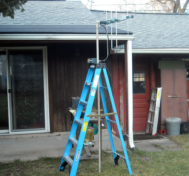
With the permanent feedline attached, I set up the antenna on a temporary 8-foot mast, using a fiberglass ladder as a support. I then moved my VHF Marine Band radio to the garden to act as a signal generator, so I could take VSWR measurements and adjust the driven element loop length. With the antenna at a height of 8-feet it should be far enough off the ground to present a reasonable radiation resistance, but close enough to reach for easy adjustment.
For VSWR check I used four frequencies: 156.05, 156.5, 157.0, and 157.4-MHz, corresponding to VHF Marine Band channels 1,10,20, and 28. This would give me coverage of the very low end of VHF Marine Band. I cannot say what the VWSR will be like at 162-MHz, but, since I only plan to receive at that frequency a slightly higher VSWR can be tolerated.
It only took four iterations of the driven element loop length to arrive at a reasonably good indication of resonance or lowest VSWR at 157.4-MHz. The VSWR was an extremely good 1.05:1 match. At the low end of the VHF Marine Band, 156.050, the VSWR rose to only 1.35:1, which is still an exceptionally good match. This is a good indication of the wide VSWR bandwidth of the antenna. (The loop element has a width of 30-5/8-inch, measured from the outer walls of the outer element sections.)
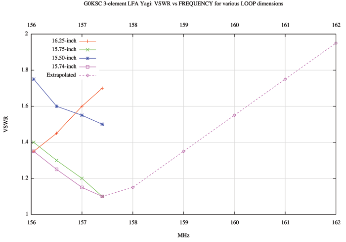
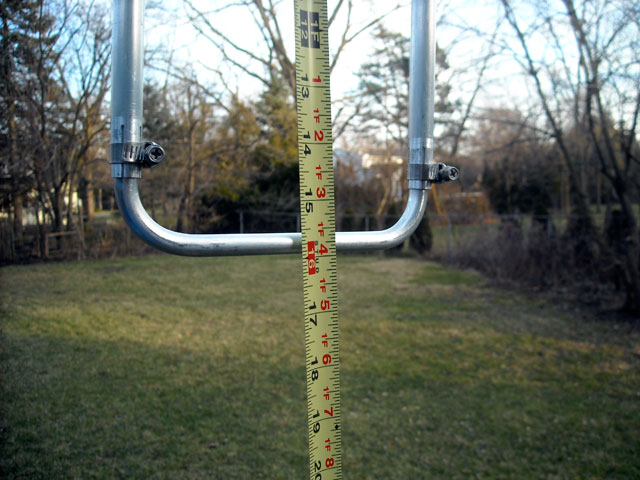
Using the radio transmitter as a signal source, I could only check the VSWR of the antenna on the low end of the VHF Marine Band. Extrapolating the VSWR curve for the final tuning (violet line), it appears the VSWR at 162-MHz could rise to around 2:1 (dashed line). The lengths refer to a distance I measured from the far side of the boom to the center of the outer element, a convenient measurement point when using a tape measure which can hook on the boom.
UPDATE: after the VSWR tests were made and the results presented above, I modified the connection of the coaxial feedline to the terminals of the antenna's driven element. The length of the connections were shortened as much as possible. The new connection is shown in the photographs above, but the VSWR measurements and antenna dimensions could not be re-tested until this Spring, due to the cold weather of winter. On re-testing I found the VSWR had changed significantly with the new feedline attachment method, and I had to retune the antenna driven element length. The new driven element length measures 16.25-inch from the far side of the boom to the center of the opposite element tube. Or, perhaps more clearly stated, the tip-to-tip measurement of the loop using the outside edge of the tube is now set for 31 and 5/8-inch. This produced a VSWR very similar to the one shown above in the violet color. The VSWR was 1.3 at 156.05-MHZ, and decreased to 1.1 at 157.40-MHz.
Because the method of attachement of the feedline influenced the VSWR curve so much, I think it is advisable to tune the driven element length by VSWR testing, rather than to just set the length to a particular measurement.
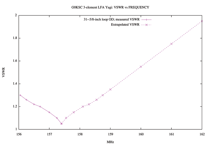
VSWR plot after the feedline connection was modified and the antenna driven element length retuned. When the feedline connection was shortened, the driven element had to be lengthened.
With the antenna only 8-feet off the ground in the garden, I used NOAA Weather Radio broadcasts as a quick check on performance. I was able to receive a weather radio broadcast on all ten channels of my VHF Marine Band radio. By changing the antenna's azimuth orientation I could find peaks and nulls on the weather stations. It was quite an impressive performance for an antenna only 8-feet high. I look forward to listening again when I have the antenna mounted higher.
I am afraid that winter weather has finally arrived here in Michigan, and the temperature drop (to 15°F) and snow fall have ended testing for the moment. I will append more information about the antenna performance as soon as the weather returns to moderate temperatures and the snow melts. There may be a lull in shipping, as typically the Great Lakes shipping season shuts down for about two months in February and March. If that happens then there won't be any AIS targets to test with, and I will have to wait until April or May of 2012 for more opportunity to test.
With the new antenna finally installed and in use for about one year, I have been very pleased with the results. I can often pick up vessels in Lake Erie, when they are in the main lobe of the antenna. A screen capture (below) shows reception at a distance of 54-miles, which I consider excellent results.
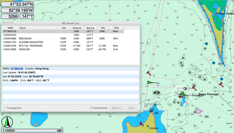
The em-trak R100 pulls in a signal using the InnovAntenna yagi at a distance of over 50-miles across urban terrain.
The G0̸KSC 3-element LFA Yagi appears to be an excellent shore station antenna for AIS reception when a directional antenna with a fairly broad pattern in its main lobe is desired. The design of the antenna is innovative, its construction is first-class, and its performance so far in initial tests has been excellent. This antenna is built for durability and endurance. The total cost of the antenna, including shipping from England and Ohio, was only $99. Considering the custom design and fabrication that went into it, the antenna is a very good value. And, since my AIS receiver was also made in England, I am certain the two will work very well together!
The page has been accessed times.
Copyright © 2012 by James W. Hebert. Unauthorized reproduction prohibited!
This is a verified HTML 4.0 document served to you from continuousWave
URI: http://continuouswave.com
Last modified:
Author: James W. Hebert
This article first appeared January 9, 2012.