MENU - PAGES
An overview is presented of the user interface structure of the Lowrance HDS SONAR and chart plotter devices which use the NAVICO operating system or NOS. An HDS-8 was used to gather the information presented here, including the many screen captures used for illustrations. The HDS-8 was using version 4.1.36.68 of the NAVICO operating system (NOS), which was the most recent release when this article was prepared.
The user interface of the HDS is separated into two major branches: menus and pages. Menus are typically overlaid onto the screen of the HDS to permit setting of options or configuration of the various components of the HDS. Pages are full-screen presentations of information; the user may interact with these pages via physical controls or on-screen soft-key controls. There are also many contextual menus which appear for individual pages. These contextual menus will be described in the corresponding PAGES information section of this document
The division of the HDS into these two major sections, menus and pages, is evidenced by the two front-panel control buttons: MENU and PAGES. The menu structure is accessed by pushing the MENU button, and the PAGES structure is accessed by pushing the PAGES button. Our documentation now branches accordingly into two sections.
MENU - PAGES
The HDS devices are complex devices which contain several instruments which share a common display screen and use common front panel control buttons. The HDS device typically contains three major components:
In addition, a number of additional external devices may be electronically connected and linked to the HDS device, including:
All of these internal and external devices make use of the HDS display screen and front-panel buttons to provide control and operation of their many functions. The HDS presents the operator with a complex and somewhat varying user interface. As some accessories are added, for example a RADAR unit, additional pages and menus will be added to the user interface. This article does not attempt to document the additional menus and pages for added devices.
Lowrance makes the HDS series in two distinct groups of models. The HDS-5 and HDS-7 models have five-inch and seven-inch display screens (respectively), and the HDS-8 and HDS-10 have eight-inch and ten-inch display screens. The HDS-8 and HDS-10 also have six push buttons below their screens for user input for functions defined on each the particular screen being displayed. The screen above each button shows the label or legend for the button, and the function of the button changes from screen to screen; in this technique the buttons are called soft keys as in software keys. This represents a major difference in the user interface between the HDS-5/HDS-7 models and the HDS-8/HDS-10 models. In the smaller models that lack the buttons, the user must push the MENU button to reveal additional menu choices for a particular screen. In the larger models with the soft-key buttons, the added menu options appear as legends for the soft keys at the bottom of the screen display. (It is important to note that in the HDS-8 and HDS-10 devices, not all of the available menu options appears on the soft keys. Pushing the MENU button will often reveal further options available to the user for a particular page.) This document describes the NOS as it appears on an HDS-8. Users of an HDS-5 or HDS-7 will not see the lower screen soft keys and will have to push the MENU key to reveal those options.
The menu structure is one branch of the two-branch fundamental structure of the user interface. The menu structure is accessed by pushing the front panel MENU button, which behaves as follows: if the MENU button is pushed once, the menu structure corresponding to the current page--a contextual menu--is selected. If the MENU button is pushed twice, the Settings menu (i.e., the root menu) is selected. (Contextual menus will be documented and explained in the PAGES section for the corresponding page they are accessed from.)
The lowest level or the root level of the menu structure is the Settings menu and is accessed from the front-panel MENU button or through other menu's options.. The Settings menu has the following branches:
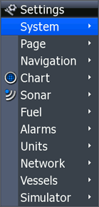
The Settings menu
I have also created a combined graphical view that shows the Settings menu and all submenus. This can be handy for a one-page reference to the menu structure and can easily be printed.
The System menu is accessed from the Settings menu and has the following branches:
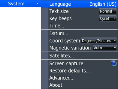
HDS System menu
The Language menu is accessed from the System menu and has the following branches, which are selected by scrolling in a pop-up window:
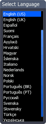
The HDS Select Language menu
The Text size menu is accessed from the System menu and has the following choices, which are selected by scrolling in a pop-up window: Normal; Small
The Key beep menu is accessed from the System menu and has the following choices, which are selected by scrolling in a pop-up window: Off; Quiet; Normal; Loud
The Time... menu is is accessed from the System menu and presents a new window. The up-down cursor keys select one of three fields. The Local time field shows the current local time as offset from UTC. The left-right cursor keys change the UTC offset in 30-minute increments. The Time format field can be set to be either 12-hour or 24-hour with a pop-up selector. The Date format field can be set to be either MM/dd/yyyy or dd/MM/yyyy with a pop-up selector. After data entry the user may choose to Save or Cancel. When the window closes the screen reverts to the previously displayed user screen, not the menu structure.
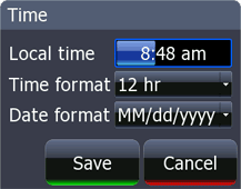
The HDS Time menu
The Datum... menu is accessed from the System menu. Choices are selected by scrolling in a pop-up window:
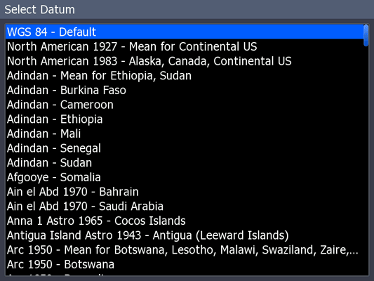
The HDS Select Datum menu
The Coord system menu is accessed from the System menu. Choices are selected by scrolling in a pop-up window:
The Magnetic variation menu is accessed from the System menu. A pop-up allows selection of Auto or Manual. If Manual is selected, a data entry window appears and the user can input a decimal value with sign. It is assumed that a positive value indicates West variation.
The Satellites... menu is accessed from the System menu and introduces an entirely new screen presenting status of the GNSS receiver that is being used, i.e., not necessarily the internal GNSS receiver but perhaps a remote receiver or a receiver in another unit. A tabular information center (right panel) gives status of the fix solution and signal strengths, deduced position, and time. A sky view polar chart (left panel) shows North at the top, East on the right. The center of the polar or azimuth and elevation chart represents directly overhead at your location; the perimeter represents the horizon. The single ring of the display is presumed to denote elevation angle 45°. Satellites in range are plotted on the az-el chart with identification by pseudo-random noise number (PRN). Satellites whose pseudo-ranges are being used in the position solution are identified with blue shading. The vertical grow bars are a relative signal strength indication (RSI) of each satellite. If a precision fix is enable and if the augmentation data from the wide area augmentation system (WAAS) is being used, the WAAS RSI bar is indicated by an asterisk, and the other satellites in the fix solution have their RSI bars also marked with an asterisk. The tabular data also shows "WAAS" in the Fix field. Configure and GPS Source buttons (lower panel) lead to more screens to select the GNSS receiver source and configure it. The pages that are linked here are actually part of the Network Data Sources... menu and Configure device sub-menu.
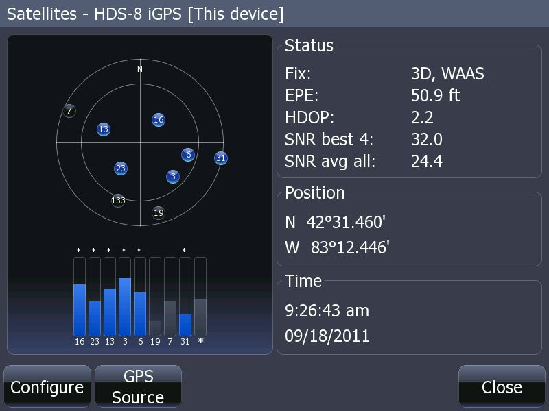
HDS-8 Satellites window. Six satellites (with PRN's 3, 6, 13 , 16, 23, and 31) are being used in the position fix solution. Satellite PRN 133 is presumed to be the WAAS signal source. The position fix precision has been augmented with WAAS.
A separate article gives more details about the Satellites information display page.
The Screen capture menu is accessed from the System menu and shows the state of the screen capture function. When screen capture is enabled, the menu bullet indicator is blue, and the front-panel LIGHT/POWER button function changes to initiate screen capture when pressed. When screen capture is not enabled, the bullet indicator is dark and the LIGHT/POWER button function controls the screen backlighting and power on-off functions. (It occurs to me that there is no way to document the menu that is presented for the power control because it cannot be captured in a screen shot!)
The Restore defaults... menu is accessed from the System menu and leads to a new window. Beginning in approximately v4.0 of the software, the Restore defaults function offers options to preserve the user's stored data for waypoints, routes, and trails while re-setting other parameters to the factory default.
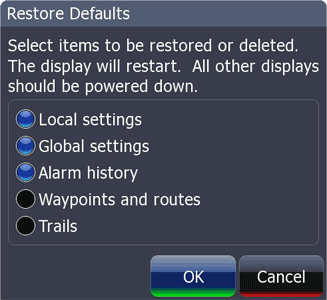
Restore defaults window offers options to select which categories of stored data
and settings will be affected during the restoration to factory default settings.
It is also possible to restore defaults by invoking certain key presses at the unit power-on. These procedures are not shown in the menu system but are given below for convenience:
The Advanced... menu is accessed from the System menu and leads to a new window, Advanced Settings, which contains a hierarchical menu structure with "+" or "-" keys to expand the structure. There are so many submenus that two images (below) are needed to show all the option. The up-down cursor keys navigate up and down the structure, while the left-right keys expand or contract the sub-menus. Once a sub-menu object is highlighted, the ENTER key is used to enable or disable the feature, and the bullet indicator shows the state. A blue bullet indicator means the feature has been enabled.
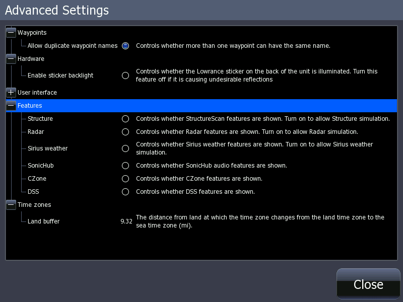
The Advanced Settings window
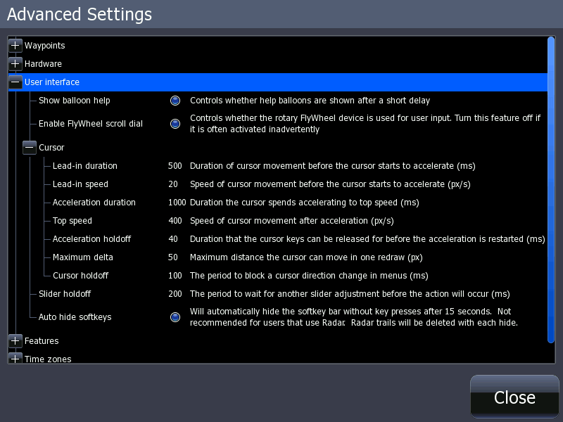
The User Interface branch of the tree is complex and is shown in this screen capture.
The About menu is accessed from the System menu and leads to a new window which presents information about the various hardware and software components of the HDS device. A typical screen capture (below) shows an HDS-8 with the version 4.1 software loaded:
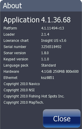
The About menu as seen on my HDS-8 device.
Lowrance cartography is loaded.
The information shown will reflect the currently loaded map cartography. To see the information on internal chart cartography, do not load cartography from a memory card. To see information about cartography on a memory card, load that cartography into the CHART page. For more information on changing the cartograply in use see the Chart options contextual menu for the CHART page.
The Page menu is accessed from the Settings menu and has the following branches:
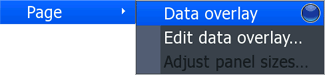
HDS Page menu
The Data overlay menu is accessed from the Page menu and enables or disables the overlay of data on the user page that is on-screen when the menu is accessed. A bullet indicator turns blue when data overlay is enable; when not enabled the bullet is black.
The Edit data overlay menu is accessed from the Page menu. When this option is selected the data overlays on the user page below become active for editing. A see-through legend appears in the upper right corner of the screen denoting "Editing overlays." A blue bounding box appears on the first screen overlay element. The left-right cursor keys move the bounding box among all data overlay elements, allowing the element to be selected for further editing. Once an element is selected, push the ENTER button to enter a new mode in which the screen position of the element can be moved with the cursor keys. With an element selected, the MENU button can be pushed to further modify the data being presented on the overlay.
The Adjust panel sizes menu is accessed from the Page menu. This menu is active only when the underlying screen is a split screen presentation. When selected, the user may adjust the position of the border between split screens, adjusting the panel size of the two screens.
If any changes are made while in the Page menu options, the user is prompted to SAVE or DISCARD the changes when the EXIT button is pushed to leave the menus.
The Navigation menu is accessed from the Settings menu and has the following branches:
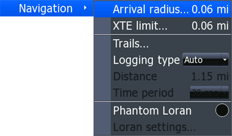
Navigation Menu
The Arrival radius menu is accessed from the Navigation menu. When selected a new window appears in which a decimal value may be entered for the tolerance of the arrival alert when a route is being navigated.
The XTE limit menu is accessed from the Navigation menu. When selected a new window appears in which a decimal value may be entered for the tolerance of the cross track error alert when a route is being navigated.
The Trails... menu is accessed from the Navigation menu. When selected the user screen jumps to the Waypoints, Routes, and Trails page with the Trails tab selected.
The Logging type menu is accessed from the Navigation menu. A pop-up permits selection of three settings: Auto, Distance, or Time. This mode selection determines the criterion for adding a new recorded point in a trail. In the Auto mode a new point is recorded whenever the boat heading changes; in Distance mode a new point is added after the boat has traveled a set distance interval; in Time mode a new point is added at a set time interval.
The Distance menu is accessed from the Navigation menu. This menu option is only available when Distance has been selected as the Logging type. When selected, a new window, Distance Period, appears and a data entry field permits entry of a decimal value for distance to be run between logging of information to the recorded Trail.
The Time period menu is accessed from the Navigation menu. This menu option is only available when Time has been selected as the Logging type. When selected, a pop-up appears and permits the time interval between logging of information to the recorded Trail to be set to a choice of 1-second, 5-seconds, 10-seconds, 30-seconds, or 1-minute.
The Phantom Loran menu is accessed from the Navigation menu and allows the Phantom Loran mode to be set ON or OFF. The menu also shows the status of Phantom Loran by an indicator bullet. When Phantom Loran mode is ON the HDS will calculate LORAN time delay (TD) from latitude and longitude, the LORAN TD will be shown along with the latitude and longitude in the cursor information pop-up on CHART pages when the cursor is active, and the bullet indicator turns blue; when Phantom Loran mode is off, the bullet indicator is black and no TD information is calculated or displayed.
The Loran settings menu is accessed from the Navigation menu. The GRI or group repetition interval is selected from a pop-up with choices as follows:
The Preferred stations value is selected from a pop-up. For LORAN chains in the USA there are preset options for preferred stations.
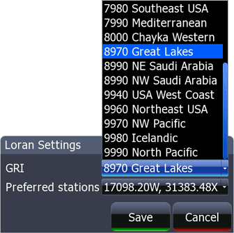
Loran Settings
The Chart menu is accessed from the Settings menu and has the following branches:
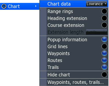
The Chart menu structure.
The Chart data menu is available from the Chart menu and allows selection of cartography to be used for display of chart data. A pop-up selector shows available choices. The digital cartography loaded into the memory of the HDS is indicated as the choice "Lowrance." This data can be either the base-map cartography or the enhanced Insight™ cartography, if available. Additional cartography choices from a memory card installed in a memory card slot will also be shown.
The Range rings menu is available from the Chart menu and controls and indicates the state of the overlay of range rings option. When enabled, the bullet indicator is blue and range rings are drawn around the current vessel position indicated on the chart display.
The Heading extension menu is available from the Chart menu and controls and indicates the state of the heading extension option. When enabled, the bullet indicator is blue and the current boat heading is extended from the current boat position indicated on the chart display with a blue graduated line. The extension length is controlled by the Extension length menu.
The Course extension menu is available from the Chart menu and controls and indicates the state of the course extension option. When enabled, the bullet indicator is blue and the current boat course over ground is extended from the current boat position indicated on the chart display with a reddish-brown graduated line. The extension length is controlled by the Extension length menu.
The Extension length menu is available from the Chart menu and is active only when an option for course extension or heading extension has been enabled. A pop-up permits selection of the length of the extension. The extension length can be set in terms of distance or time. The distance options are 1-mile, 10-miles, and 100-miles. The time options are 1-minute, 2-minutes, 10-minutes, 30-minutes, 60-minutes, and 120-minutes. Another option, Constant, draws an extension line to the edge of the screen no matter what the scale of the chart display.
The Popup information menu is available from the Chart menu and controls and indicates the state of the popup information option. When enabled, the bullet indicator is blue and additional information about objects seen on the chart will popup in a translucent shaded window for three seconds when the cursor is moved over the object.
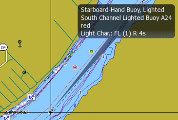
Popup information about an aid to navigation.
The Grid lines menu is available from the Chart menu and controls and indicates the state of the option to display grid lines of latitude and longitude on the chart display.
The Waypoints menu is available from the Chart menu and controls and indicates the state of the option to display the user's waypoints on the chart display. When enabled, the bullet indicator is blue and user's waypoints will be seen on the navigation chart display.
The Routes menu is available from the Chart menu and controls and indicates the state of the option to display the user's routes on the chart display. When enabled, the bullet indicator is blue and user's routes will be seen on the navigation chart display.
The Trails menu is available from the Chart menu and controls and indicates the state of the option to display the user's trails on the chart display. When enabled, the bullet indicator is blue and user's trails will be seen on the navigation chart display.
The Hide chart menu is available from the Chart menu and controls and indicates the state of the option to display the chart cartography on the chart display. Turning off the chart cartography will still leave other chart elements visible, such as user's waypoints, routes, and trails.
The Waypoints, routes, and trails... menu is a short cut to the Waypoints, routes, and trails user page.
The Sonar menu is accessed from the Settings menu and has the following branches:
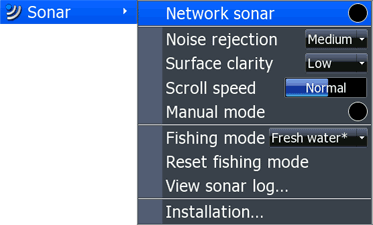
The Sonar menu structure.
The Network sonar menu is available from the Sonar menu and controls and indicates the state of the option to network the SONAR information from the HDS device to other connected Lowrance devices on the Lowrance Ethernet network for remote display. When enabled, the bullet indicator is blue and SONAR information will be shared from this device to the Lowrance Ethernet network and attached devices.
The Noise rejection menu is available from the Sonar menu and controls the settings for noise rejection filtering in the SONAR. A pop-up menu selector allows options for Off, Low, Medium, High noise rejection.
The Surface clarity menu is available from the Sonar menu and controls the settings for surface clarity filtering in the SONAR. A pop-up menu selector allows options for Off, Low, Medium, High surface clarity filtering.
The Scroll speed menu is available from the Sonar menu and controls the settings for the speed of the horizontal scrolling of the SONAR display. After navigating to this menu, the scroll speed is changed by using the [CURSOR-RIGHT] or [CUSROR-LEFT] keys to alter the scrolling speed, and the menu indicator grows or shrinks with a horizontal grow bar to visually indicate the setting. A legend for the setting also appears in the grow bar. The speed can be varied from x 1/8 to NORMAL to x 8.
The Manual mode menu is available from the Sonar menu and controls and indicates the SONAR mode setting. When manual mode is enabled, the bullet indicator is blue and the SONAR mode is changed to an advanced user mode. When disabled the indicator is black and the SONAR mode returns to the normal state.
The Fishing mode menu is available from the Sonar menu and permits selection of the SONAR to pre-configured settings for particular types of fishing use. The options are General use, Shallow water, Fresh water, Deep water, Slow trolling, Fast trolling, Clear water, Ice water. Each mode provides pre-set options for the color palette, sensitivity, interference rejection, surface clarity, and ping speed, as well as other pre-sets.
The View sonar log... menu is available from the Sonar menu and jumps a new window, Sonar Files, where the user can select recorded sonar log files for viewing.
The Installation... menu is available from the Sonar menu and jumps a new window, Sonar Installation, where the user can enter settings for the SONAR.
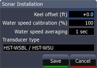
Sonar Installation window
A value for Keel offset can be entered to compensate for the position of the transducer relative to either the keel (a negative offset) or the waterline (a positive offset). The Keel offset value is algebraically added to the depth measured by the SONAR before it is displayed on screen.
A value for Water speed calibration (%) can be entered to improve the accuracy of the boat speed through the water as measured by the paddlewheel sensor. If the paddle wheel sensor speed is too low, set the offset to values above 100. If the paddle wheel sensor speed is to high, set the offset to values below 100.
A value for Water speed averaging can be entered to modify the interval at which water speed readings are sampled and averaged. The input field shows a horizontal grow bar and also displays the value selected. The range is from 1 second to 30 seconds in 1-second increments.
A value for Transducer type can be entered using a very long list of choices. The value selected should match the transducer being used. Highlight the field and press ENTER to see the choices. (Note: Lowrance transducers are usually identified by a foil label attached to their connecting cable near the connector end.)
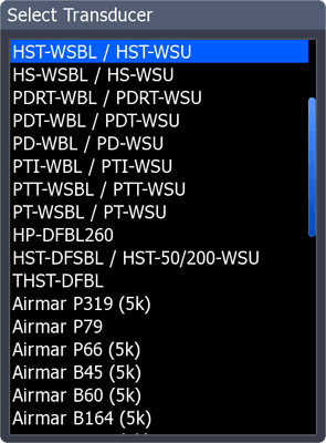
Select Transducer window
The Fuel menu is accessed from the Settings menu and has the following branches:
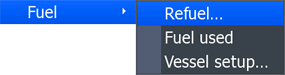
The Fuel menu.
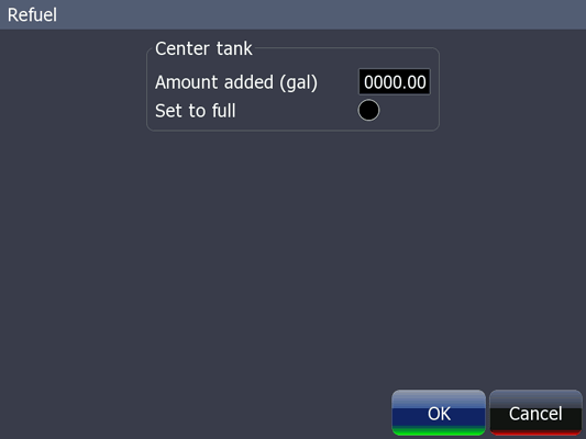
The Refuel... menu is available from the Fuel menu and jumps a new window, Refuel, where the user can enter data about fuel volume added to tanks.
Refuel window.
The Fuel used menu is available from the Fuel menu and jumps a new window, Fuel used, where the user can see information about fuel usage. Fuel usage is accumulated and tracked by three counters: Since last fill, Trip, Seasonal. The Reset... option leads to a new window, Reset, where the accumulators can be reset.
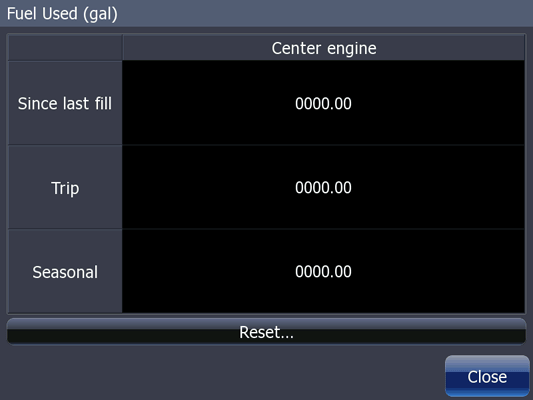
Fuel used window.
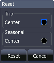
[Fuel] Reset window.
The Vessel setup... menu is available from the Fuel menu and jumps a new window, Vessel setup, where the user can configure the HDS fuel management function. The Vessel configuration can be set to one of six combinations of one, two, and three engines and one, two, and three tanks. The capacity of each tank can be set in the appropriate units. A Calibrate option leads to the Flow Device Calibration window, where information on how to perform calibration of the fuel flow device being used is given.
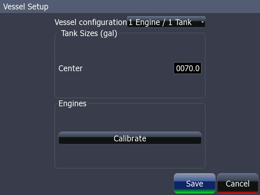
Vessel setup screen
The Alarms menu is accessed from the Settings menu and has two branches: Settings... and Siren enabled.
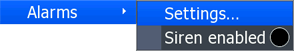
Alarms menu
The Settings... menu (i.e., the Alarm Settings...menu) is accessed from the Alarms menu and leads to a new window, Alarms. The window has three tabs: Active, History, Settings. The Active window shows the alarms which are currently activated. The History tab shows the history of alarm activity. The Settings tab controls which alarms are enabled and sets the threshold limits for alarms. Enabled alarms are indicated by a blue bullet.
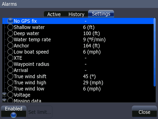
The Alarms window; the Settings tab is shown.
The Siren enabled menu is accessed from the Alarms menu and controls the siren or aural alert function. When enabled, the bullet indicator is blue, and at the onset of an alarm an aural alert tone is sounded.
The Units menu is accessed from the Settings menu and presents twelve sub-menu with these settings choices:
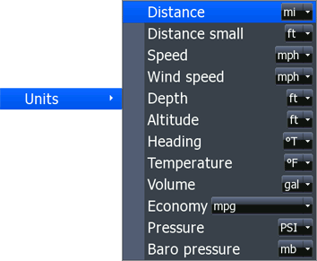
The Units menu and its sub-menus.
The Network menu is accessed from the Settings menu and presents six options:
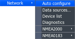
The Network menu and its sub-menus.
The Auto configure menu is available from the Network menu. When Auto configure is selected, all data sources will be reset to default settings, and all instances will be removed from HDS networked devices.
The Data sources... menu is available from the Network menu and allows selection of data sources. A typical use is to select the source for GPS data on a network which contains more than one GPS receiver source.
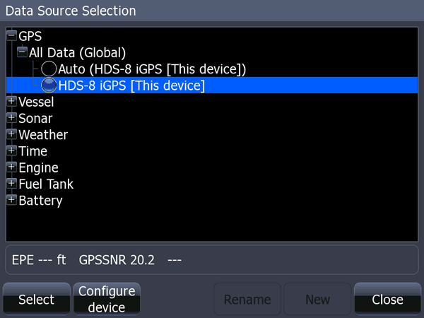
The Data Sources menu, with expansion on GPS branch of the tree structure.
If the data source device offers some configuration options, there will be a button with legend Configure device shown in at the bottom of the screen. Selecting this button will lead to a new page with options to configure the device. GPS devices typically offer the option to enable precision fix augmentation.
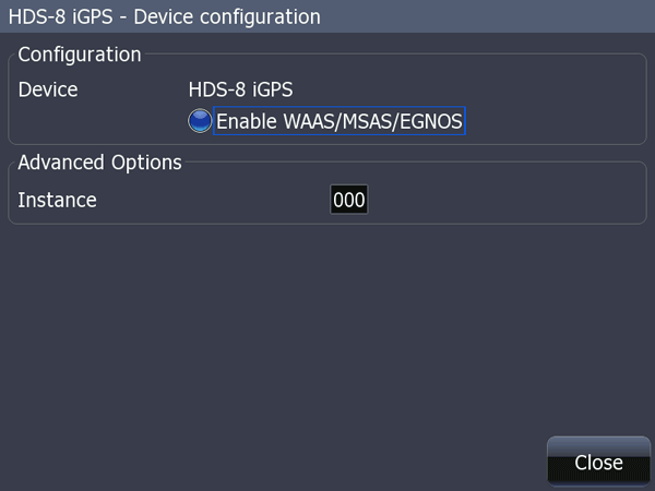
The device configuration nemu for the internal GPS receiver in an HDS-8; here the option
to enable or disable WAAS precision fix augmentation is provided.
The Device list menu is available from the Network menu and displays a listing of all devices connected to the NMEA-2000 network.
The Diagnostics menu is available from the Network menu and permits viewing of data transmission statistics for the NMEA-2000 network and the UBD (Ethernet) network via two tabs.
The NMEA 2000 menu is available from the Network menu and controls options for sending and receiving waypoint data on the NMEA-2000 network, and for controlling the backlight synchronization function.
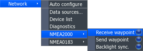
HDS NMEA 2000 menu
The NMEA 0183 menu is available from the Network menu and permits configuration of the serial ports, their baud rates, and the data sent on them using several additional sub-menus.
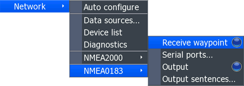
HDS Network Menu, NMEA-0183 submenu
The Receive waypoint option enables waypoint data to be received on a NMEA-0183 serial port. If enabled the bullet indicator is blue and the HDS will listen for waypoint data sent from another device on the serial port(s). If not enabled the bullet indicator is dark and the HDS will not listen for waypoint data on the serial port(s).
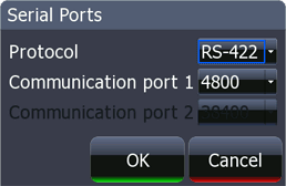
The Serial ports... menu choice presents a new window in which the serial ports of the HDS can be selected to be either a single RS-422 differential port, or to be two RS-232 single-ended ports. Use the pop-up selection in the Protocol field to make the selection. Set the baud rate for a port in the Communication port 1 or Communication port 2 pop-up.
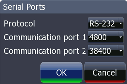
HDS Network Menu, NMEA-0183 sub-menu, RS-232 sub-menu.
If RS-232 is selected in the Protocol field, two serial ports are available and can be set to different baud rates. In the example above Communication port 1 is set to 4800, the standard NMEA rate, and Communication port 2 is set to 38400, the fast NMEA rate used by AIS receivers. The function of the associated wires in the Data Cable will change to reflect this setting.
HDS Network Menu, NMEA-0183 sub-menu, RS-422 sub-menu
If RS-422 is selected in the Protocol field, only Communication port 1 is available and can be set to a single baud rate. The function of the associated wires in the Data cable will change to reflect this setting.
The Output option enables data to be sent on a NMEA-0183 serial port from the HDS. If enabled the bullet indicator is blue and the HDS will send data to other devices on the serial port(s). If not enabled the bullet indicator is dark and the HDS will not send data on the serial port(s).
The Output sentences... menu option presents a new window in which the NMEA-0183 datagrams which will be sent can be selected from a listing. The datagrams are listed by NMEA-0183 acronym designators. A blue bullet indicator means the datagram will be sent. Use the cursor keys to scroll vertically and horizontally in the heirarchical structure. Use the ENTER key to toggle the state of the function.
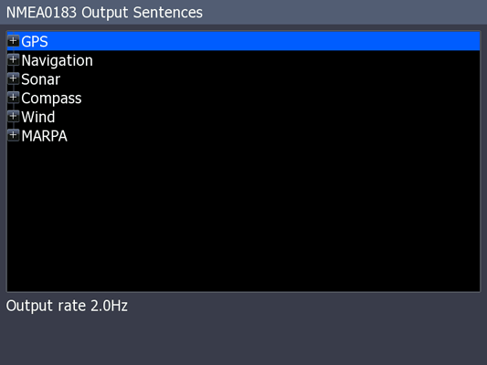
HDS NMEA 0183 Output sentences window; the several subcategories of data can be expanded.
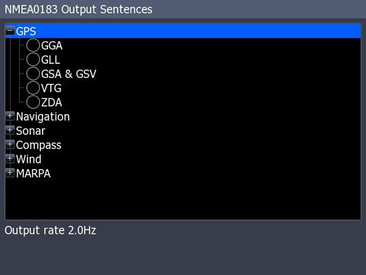
HDS NMEA 0183 Output sentences window; the category GPS has been expanded.
No datagrams are selected for output in this view.
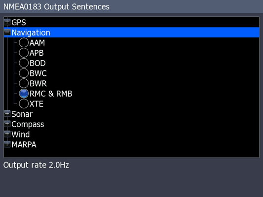
HDS NMEA 0183 Output sentences window; the category Navigation has been expanded.
The datagrams RMB and RMC are selected for output in this view.
The Vessels menu is accessed from the Settings menu and presents four options:
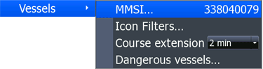
The Vessels menu and its sub-menus.
The MMSI menu is accessed from the Vessels menu and permits entry of and displays the vessel's marine mobile service identity (MMSI).
The Icon filters... menu is accessed from the Vessels menu and permits selection of various filters to hide the plotting of AIS target vessels on the chart plotter screen based on the target vessel's distance, the target vessel's speed, the risk of collision with the target vessel, or to hide all vessel icons.
The Course extension menu is accessed from the Vessels menu and permits selection of how the course extension of AIS target vessels will be projected. There are options for time and distance.
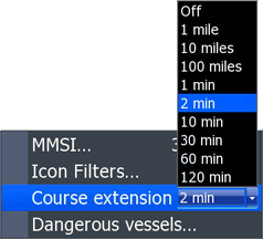
The Course extension menu and its pop-up choices.
The Dangerous vessels... menu is accessed from the Vessels menu and permits setting the criteria for marking an AIS target vessel as dangerous based on its predicted closest point of approach and time to the closest point of approach.
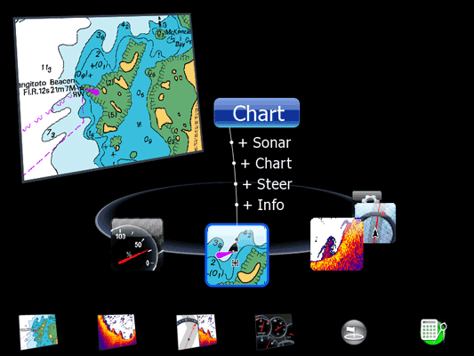
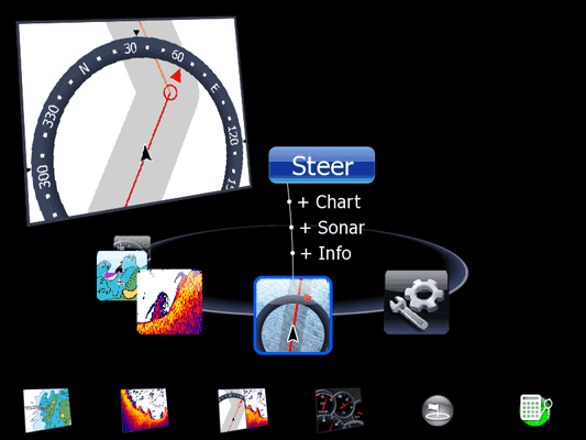
The PAGES branch of the user-interface structure is reached by pushing the front panel PAGES button. There are five major branches of the PAGES structure:
Note: the user interface does not give a name heading to the fifth branch, but Lowrance refers to this as the UTILITIES page. The name "Utilities" does not appear on screen on the HDS, however, this major branch is represented graphically with an icon that shows a gear and a wrench, and hence the UTILITIES name.
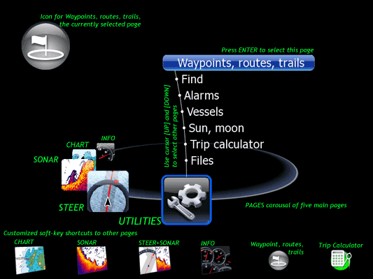
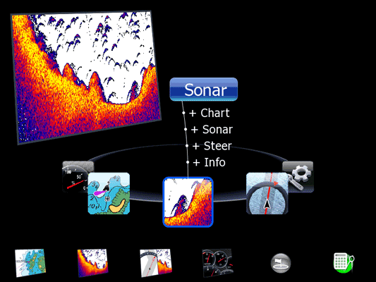
One of the five navigation screens for the PAGES carousal, with annotations.
When the PAGES button is pushed, the user may navigate through the five major branches by horizontally scrollling through them in an endless loop or in the manner of a carousal, that is, the choices rotate around, repeating the five major branches over and over. The carousal rotates or horizontally scrolls with each push of the PAGES button or by using the [CURSOR-RIGHT] and [CURSOR-LEFT] keys. If the ENTER button is pushed, the HDS jumps to the selected page. At each of the five top-level choices, several sub-level choices are also presented. The sub-level choices permit the arrangement and selection of split-screen displays for the INFO, CHART, SONAR, and STEER gpages, and for selection of seven additional pages on the UTILITIES option.
This user interface is a source of continual confusion. After the [UP] and [DOWN] cursor buttons are used to navigate among choice, there is a natural tendency to push the [RIGHT] cursor to select the choice. Pushing the [RIGHT] cursor button does not select the choice; instead, it rotates the page carousal. To select a choice the user must push the ENTER button.
In a tabular manner the PAGE carousal appears like this:
This section is under construction and only some of the PAGES are fully explained at this moment. For each page there is a corresponding contextual menu or menus which presents additional options for the user interface. Fortunately, most of the contextual menus are not difficult to understand or to use.
The INFO carousal screen is one of the rotations on the PAGES carousal; it permits selecting the INFO page as a full screen page, or permits creation of a split-screen display with the INFO page on the left side and either the CHART, SONAR, or STEER page on the right side.
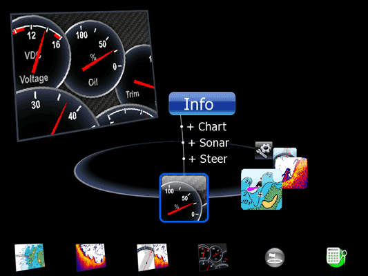
The INFO position on the PAGES carousal rotation
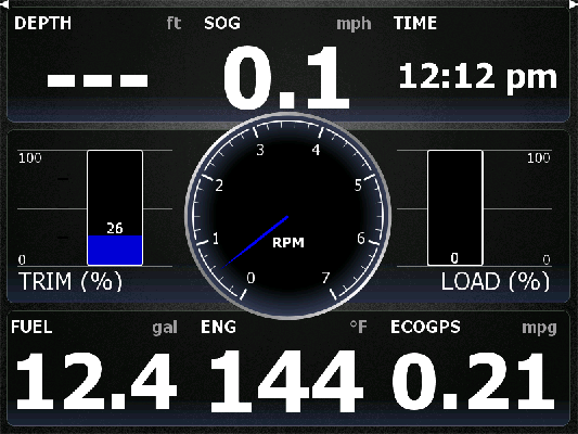
A typical INFO page showing a variety of data sources. Note the arrows in the upper corners.
The INFO page is selected from the PAGES carousal and displays data about the engine, the environment, the navigation, and various other data sources on the vessel in a vareity of presentations (called "dashboards") using round pointer gauges, grow bars, or numeric display. There are three pre-configured stored "dashboard" sets, and the user can cycle among these by using the LEFT-RIGHT cursor keys. The user can customize or modify these dashboards, selecting the style, changing the data presented, and the manner of presentation; the user can also add more dashboards to be saved and included in the selection options. Curiously, on the INFO page the six soft keys become non-functional. Pushing the MENU button reveals the contextual menu.
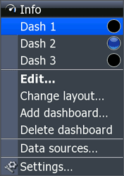
The INFO page contextual menu.
The INFO page contextual menu provides an alternative method to navigate among the stored dashboards with the Dash 1, Dash 2, and Dash 3 bullets which are also indicators. Selecting Edit... makes the current dashboard change to an edit mode. In edit mode, by using the cursor keys to navigate the user can select among the various screen objects to be editied. Once an object is selecting, pressing ENTER produces a data selection window, and the user can choose the data to be displayed by the screen object.
The Change layout... option leads to the Change Dashboard window, where a layout of screen objects for the dashboard may be selected from three different pre-configured panels called Vessel, Navigation, and Angler.
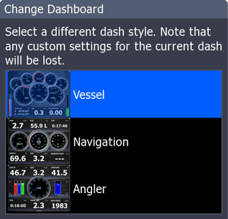
The Change Dashboard contextual menu.
The CHART carousal screen is one of the rotations on the PAGES carousal; it permits selecting the CHART page as a full screen page, or permits creation of a split-screen display with the CHART page on the left side and either the SONAR, CHART (that is, a second CHART page), STEER, or INFO page on the right side.
The CHART position on the PAGES carousal rotation
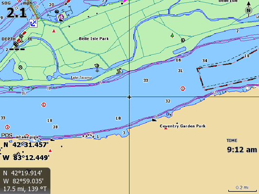
The CHART page. Data overlays for SOG, Depth, Position and Time have been added.
The cursor has been activated and its cross-hairs appear. The shaded box at lower left
shows the cursor location.
The CHART page is selected from the PAGES carousal and shows an electronic chart presentation. There are two modes of display: normal and cursor. The chart display is normally oriented based on the current position of the vessel. If the cursor keys are touched, the cursor mode becomes active; the cursor keys can be used to move the chart display away from the current position. In cursor mode a cross-hair appears on screen and the position of the cross-hair and the distance and bearing to the cross-hair from the current position is indicated in a shaded box, as shown in the illustration above. Press the front-panel button EXIT to toggle between cursor mode and normal mode on the CHART page.
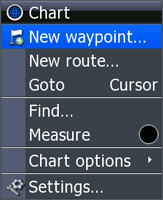
The CHART contextual menu.
Hitting the MENU button reveals the CHART page contextual menu. New waypoint... jumps to the New Waypoint at Vessel data entry window, and the user can create a navigation mark at the current position, with an option to edit the name of the mark. New route... adds a confusing overlay of route editing controls, not fully understood or appreciated. Find... jumps to the Find window. Measure initiates a measuring device from the current position to the cursor, which can be moved around to produce distance and bearing measurements to other locations.
If the cursor is over a chart object for which additional informatiokn is available, the Info option will appear. If selected, a Chart Info window about the chart object under the cursor appears and can be navigated to find more information.
Chart option introduces a new sub-menu with many further choices.
The contents of the Chart options sub-menu will depend on the details and options of the electronic chart in-use when the menu is selected. The more options available on a particular chart, the choices presented in the sub-menu, including the choice to select further sub-menus to continue configuration.
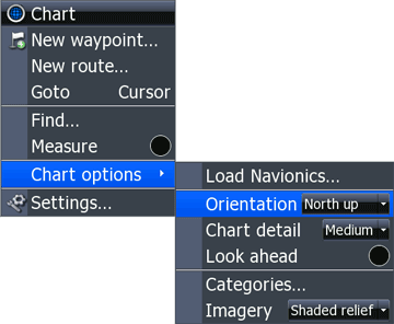
The Chart Option sub-menu with a Lowrance chart loaded.
If alternate electronic chart cartography is available, the Chart options menu will offer an option to load the alternative chartography. In the example above, the menu option is Load Navionics... because the current cartography being used was the Lowrance data and a memory card containing Navionics data was available.
Orientation permits selection of the chart orientation from options for North up, Heading up, and Course up.
Chart detail permits selection of the chart detail level from options for Low, Medum and Full.
Look ahead toggles the chart display to shift the vessel location from center screen to one favoring showing more chart information in the area ahead of the vessel on its current course.
Categories... leads to a new window, Chart Categories where the user can select whether to display chart objects. The categories are:
In each category there are extensive sub-categories which may be individually selected for display or supression.
Imagery permits selection of the chart image presentation from options for 2D, Shaded relief and No contours.
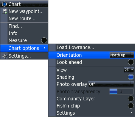
The Chart Option sub-menu for a Navionics Chart.
If the chart cartography in use supports further options, the options will appear in the Chart options sub-menu. Typical options permit selection of a presentation with either 2D or 3D view, and shading of chart objects to enhance perspective. Options available will vary with the features of the digital chart cartography in use. In the example shown above, there is an option to select another sub-menu, which contains even more options.
The SONAR carousal screen is one of the rotations on the PAGES carousal; it permits selecting the SONAR display as a full screen page, or permits creation of a split-screen display with the SONAR page on the left side and either the CHART, SONAR (that is, a second SONAR page), STEER, or INFO page on the right side.
The SONAR position on the PAGES carousal rotation
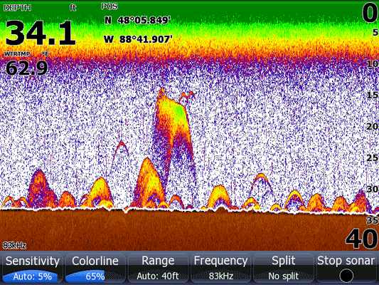
The SONAR page
The SONAR page displays the usual presentation of SONAR echograms, with older data scrolling off the screen at the left and new data coming onto screen at the right. On the HDS-8 and HDS-10 models, the six soft key buttons are available to modify the screen presentation. Hitting the MENU key produces this contextual menu of options.
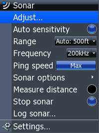
SONAR contextual menu.
The Adjust ... menu option causes a pop-up to appear on screen, in which the user can select either settings for SONAR gain or SONAR colorline parameters with the UP-DOWN cursor keys, and adjust the value of the parameter with the LEFT-RIGHT cursor keys. Press EXIT to leave the pop-up menu.
The state of Auto sensitivity is indicated and controlled by this menu option. When auto sensitivity is selected the bullet is blue. If auto sensitivity is enabled, the range of adjustment available to the operator is limited.
The parameters for Range can be set in this pop-up selection menu. There are choices for settings of 500, 400, 300, 250, 200, 150, 120, 80, 60, 40 30, 20, 15, 10, 8, and 5-feet, or Custom. If Custom is selected, the Custom Range window appears; the upper and lower limits of a depth range can be set using numerical entry windows and the cursor keys.
The SONAR frequency can be set to either 200-kHz, 83-kHz, or 50-kHz in this sub-menu. The frequencies available depends on the transducer in use.
The SONAR pulse rate is controlled by the Ping Speed menu. Ping speed is shown in a horizontal grow bar. The LEFT-RIGHT cursor keys control the setting. Higher ping speeds are useful when the boat is moving at higher speeds.
The Sonar options menu option leads to a new window, the Sonar options window.
Sonar Options contextual sub-menu.
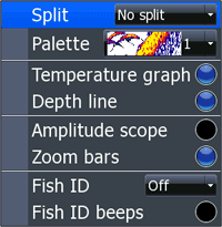
The Split menu provides four choices for split-screen display: No split, Zoom, Bottom Lock, and Flasher. The Palette menu offers the choice of color palette for the echogram display; there are 14 palettes available. The Temperature graph option draws a horizontal line on the display near the top to represent water temperature. The Depth line option enhances the echogram display with a distinct black-line marking the sea bottom. Amplitude scope places the traditional A-scope display on the right of screen. Zoom bars are used in Split mode and mark the portion of the water column to be seen in the zoom window. Fish ID marks the echogram with icons for echoes likely to be fish. Fish ID beeps sounds an aural alert when an echo that is likely to be a fish is detected.
The option to measure distance on the echogram screen is controlled and indicated by the blue bullet. When Measure distanc is enabled, cross hairs appear on the echogram display and can be used to measure distance and bearing from the boat's current position to the postiion of an echo shown in the past on the echogram display.
The SONAR pinging may be halted with the Stop Sonar menu. When the SONAR is stopped, the legend Stopped appears on the echogram display.
Selecting the Log Sonar... option presents a new sub-menu window. A text entry window allows the SONAR log Filename to be entered. The storage volume for the SONAR log file can be selected to be either the internal memory or an external memory card in the Save to pop-up. The Bytes per sounding can be selected from a pop-up with choices of 100, 200, 400, 800, 1200, 1600, 2000, 2400, 2800, or 3200. The option to Log all channels of data in the SL2 format can be enabled. The Time remaining value estimates the amount of space available for a recording with the selected parameters in hours, minutes, and seconds.
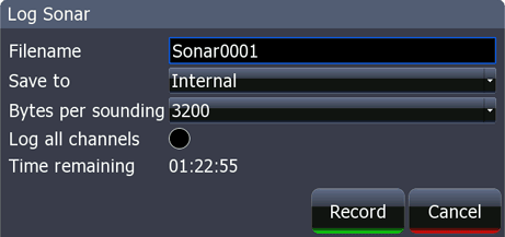
Log Sonar contextual sub-menu.
The STEER carousal screen is one of the rotations on the PAGES carousal; it permits selecting the STEER display as a full screen page, or permits creation of a split-screen display with the STEER page on the left side and either the CHART, SONAR, or INTO page on the right side.
The STEER position on the PAGES carousal rotation
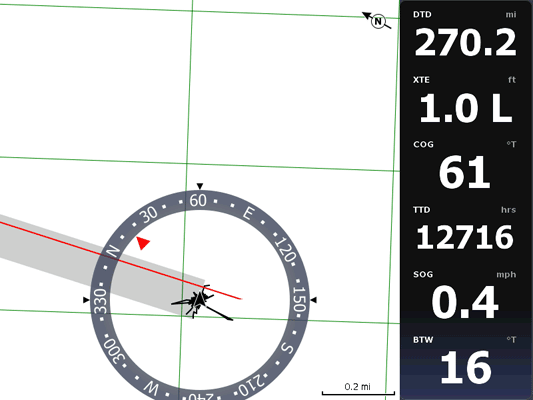
The STEER page, showing a course-up view. The current course is 61° and the bearing
to the destination is 16°. A left turn of 45-degrees is needed to correct the course.
The STEER page presents a split screen display. On the right is a listing of parameters for the navigation toward a waypoint:
On the left is a course-up display of the navigation, showing the boat's current heading, the course to steer to the next waypoint, and the distance away from the original track.
Pushing the MENU button on the STEER page reveals the contextual menu. There are only three options. Start route... reveals the Select Route menu, from which a route can be selected from the stored routes. Goto waypoint... reveals the Select Waypoint menu, which contains a listing of all waypoints and, unfortunately, all route points, mixed together in an alphabetical listing. Choosing Settings... branches to the Settings menu.
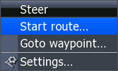
STEER Contextual menu
If there is an active route, three additional options appear on the contextual menu: Skip, Cancel, Restart.
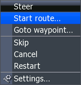
STEER Contextual menu with active route
The UTILITIES screen is different than the other options on the PAGES carousal; instead of presenting options for split screen pages, the UTILITIES option presents a list of seven alternative pages:
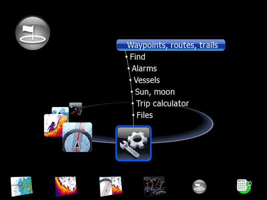
HDS UTILITIES page on the PAGES carousal
The Waypoints, routes, trails page is selected from the UTILITIES option of the PAGES carousal. The page contains three tabs:
The horizontal cursor keys are used to change the tab selection. Within a tab, the vertical cursor keys are used to scroll the lists.
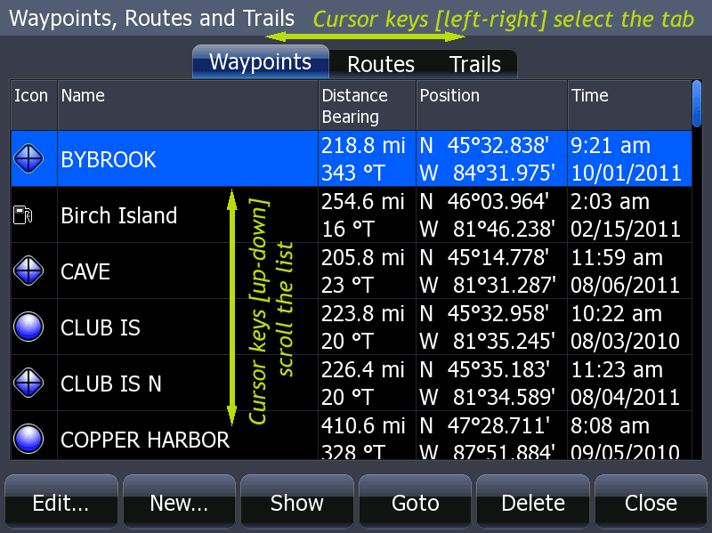
HDS Waypoints, routes, trails page with annotations.
The Waypoints tab is accessed from the Waypoint, Routes and Trails page and presents a table of waypoint information. The data in the columns for Icon, Name, and Position can be edited. The Distance Bearing column computes the range and bearing to the waypoint from the current position. The Position column gives the latitude and longitude coordinates for the waypoint. The Time column gives the date and time the waypoint was created.
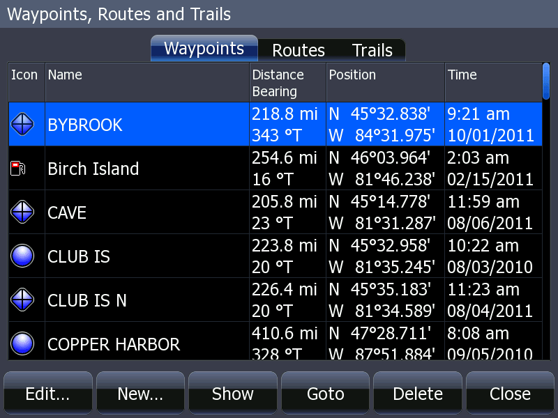
HDS Waypoints, routes, trails page with Waypoint tab selected.
A stored waypoint may be edited by pushing the softkey Edit... A new window appears, the Edit Waypoint window.
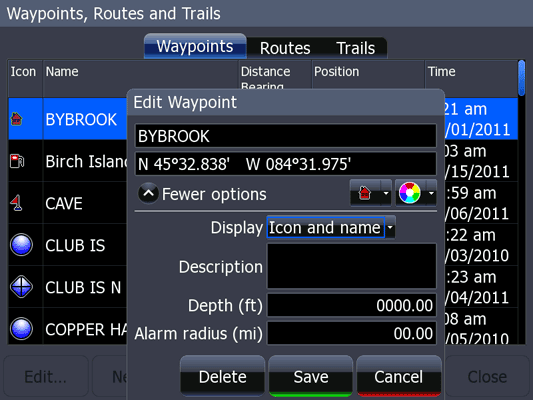
Edit Waypoint window.
In the Edit Waypoint window a number of fields may be edited. Use the cursor keys to navigate among the fields. The waypoint name and its geographic coordinates may be edited with text and numbers. The icon shape and its color may be edited by selection from palettes. Expanding the window to show more options reveals additional parameters. The Display parameter can be selected from a pop-up menu. There are three choices: Off, Icon, Icon and name. These display options can be set for individual waypoints. Descriptive text can also be added to the Description field. This text will only appear on the chart display if the user selects the INFO option when the cursor is over the waypoint. Parameters for the water depth at the waypoint and the arrival alarm sensitivity can also be added and edited.
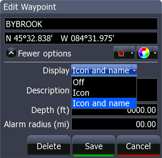
Display pop-up choices
Display options can be set for each stored waypoint. Note that there is a global setting for display of waypoints in the Waypoints menu.
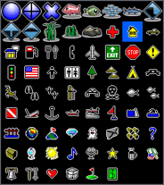
Display Icon palette choices
The icon used to mark a waypoint can be selected from a palette of choices. The color of the icon can also be changed.
A new waypoint can also be created in a similar manner by pressing the New... softkey.
The Routes tab is accessed from the Waypoint, Routes and Trails page and presents a table of route information. The width of the Name column is fixed at 16-characters. This should be considered when assigning names to routes that are created with other devices. Long names are truncated. The Start and End columns show the name of the route point at the starting and ending points of the route; these names may not have much information value. The Legs column shows the number of segments in the route. The Distance column gives total distance of the entire route. The Edit option allows the route name to be changed. It also allows the individual route to be selected for display. The route is shown on the chart plotter when the display option is enabled. Note there is a global setting for display of routes in the Routes menu.
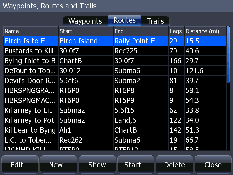
HDS Waypoints, routes, trails screen with Routes tab selected.
The Trails tab is accessed from the Waypoint, Routes and Trails page and presents a table of information showing the display status, recording status, trail name, color of the track line, and number of points contained in the trail. Trails are a logged track of the vessel movement. Several on-screen soft keys offer options, but even more options are available if the MENU button is pushed.
If the MENU button is pushed, a new submenu appears, containg an option for a global setting for trails to be shown, an option for a global setting for trails to be recorded, and a new submenu, SETTINGS. These same options appear in several other menus.
In the new sub-menu SETTINGS there is a further menu choice, LOGGING TYPE, for the method for logging a point in the trail. These same settings are also found elsewhere in the user interface and are described in the section on the Settings Menu and its Navigation sub-menu. The Logging type option controls the critereon for adding a point to the logged trail.
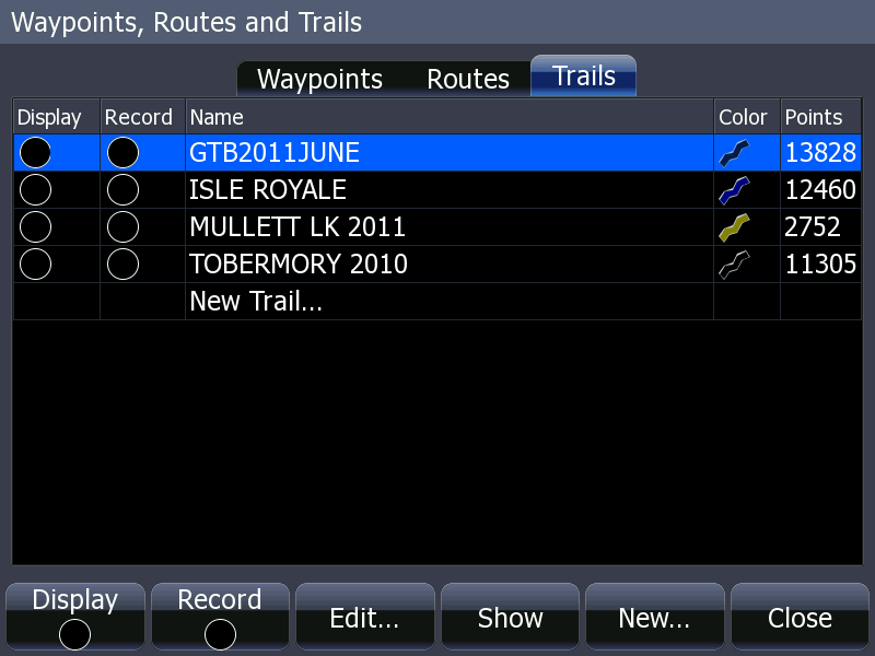
HDS Waypoints, routes, trails screen with Trails tab selected.
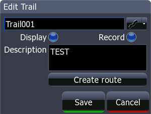
The diplay and record parameters can be easily toggled using soft keys. Note there is a global setting for display of trails in the Trails menu. Selecting the Edit... option introduces a new window, Edit Trail.
Edit Trails.
In the Edit Trail window the name of the trail can be modified and descriptive text added. The color of the trail can be changed by selection from a pop-up menu of choices. The Create route option offers to create a new route by using the trail points as route points. Depending on the number of trail points in a trail, a route created from a trail could be rather complex.
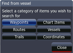
The Find page is selected from the UTILITIES option of the PAGES carousal.
The Alarms page is selected from the UTILITIES option of the PAGES carousal. The Alarms page can also be accessed from the MENU options.
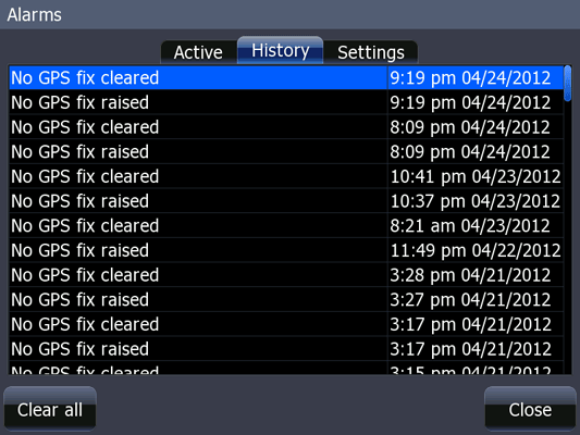
The HDS Alarms page; shown on the history tab. A number of No-Fix alarms are recorded.
The Vessels page is selected from the UTILITIES option of the PAGES carousal.
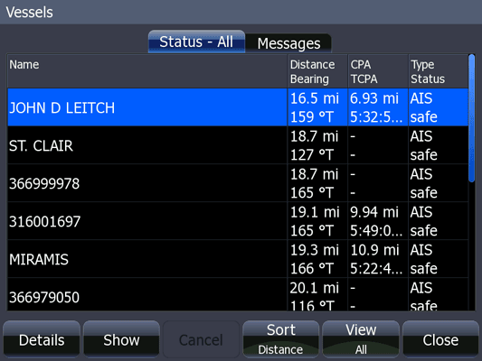
HDS Vessels page; the listing shows vessel data received from an automatic identification system receiver.
The Sun, moon page is selected from the UTILITIES option of the PAGES carousal.
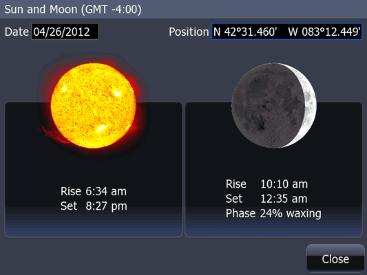
HDS Sun, Moon page.
Note that the Sun, moon page can be used to predict solar and lunar astronomical calculations at other places and times by changing the date and position. Scroll to either field and press ENTER to change the Date or Position from the current date and position.
The Trip Calculator page is selected from the UTILITIES option of the PAGES carousal.
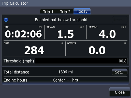
HDS Trip Calculator page. There are three tabs, one for each trip mileage oddometer function.
The Trip Calculator only accumulates distance to its tracking when the boat speed is above the Threshold value set in the data entry window.
The Files page is selected from the UTILITIES option of the PAGES carousal.
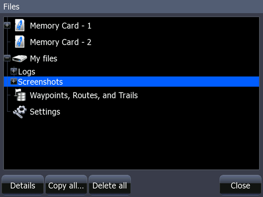
The HDS Files page.
If the user browses to the Waypoints, Routs, and Trails selection, a new option appears, Export. If Export is selected, a new window appears, Export Waypoints, Routes, and Trails and permits the user to export data from the HDS for waypoints, routes, and trails to an archive file or to the serial ports.
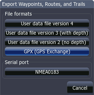
HDS Export Waypoints, Routes, and Trails menu
The format of the archive file can be selected from options:
Selecting one of the four file format choices results in a prompt to select a destination folder (or path) for the new file that will be created, followed by another window in which the file name can be selected or created.
If, instead of a file format, Serial port/NMEA-0183 is selected the waypoints and routes are sent to the (serial port or both serial ports if the HDSD is configured for two) serial ports. The data is sent in datagrams using a format similar to NMEA $GPWPL and $GPRTE, but the datagrams use $CPWPL and $CPRTE as the identifer of the messages. Here we infer that $CP means "chart plotter." From looking at the exported data on the serial ports, it appears the names of waypoints or routes are truncated to the first eight characters during the export process. It also appears that route points in the routes are exported as waypoints.
If the user browses to the Settings option, the device settings can also be exported to a file. Settings file archives have a .set suffix.
If a memory card is inserted that contains a recognized file, i.e, a file with a suffix of .usr, .gpx, or .set, the data in the file can be loaded into the HDS by selecting the Import option, which appears when the appropriate file is highlighted in the file navigation process.
For every page display there are menus specific to that page; these are called contextual menus. Inasmuch as there are dozens and dozens of these, at this writing this guide does not document all of the contextual menus. Contextual menus are explained in the section associated with their parent page. A few unusual contextual menus will be described in detail below.
Beginning with software version 4 of the NAVICO operating system, the HDS-8 and HDS-10 devices acquired a very strong user interface feature on the PAGE selection carousal: soft key shortcuts were added which permit the user to jump to any of the options of the PAGE carousal. The method of configuration of the soft keys is described below.
At the bottom of the PAGES display on the Lowrance HDS-8 and HDS-10 there are now six small trapezoidal bounding areas (apparently designed to continue the 3D or perspective view of the overall PAGES theme) which appear across the bottom of the display and above the six hardware buttons below the display. The bounding areas are blank, and they are intended to be legends or identifiers for the hardware buttons below them.
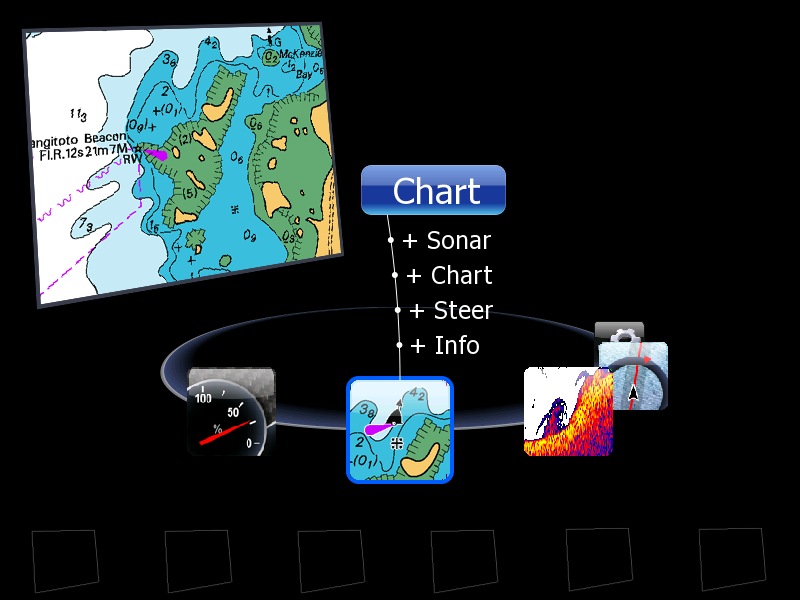
HDS PAGES with soft key shortcuts blank and ready for selection
If one pushes a hardware button below a blank trapezoid, and if the HDS's NOS is set for the HELP ballon feature to be ON, the following message will appear: "Hold to save the highlighted page".
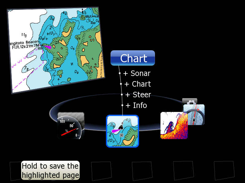
HDS PAGES shortcuts saving new shortcut. The shortcut will jump to the highlight page, CHART.
Indeed, if one holds down the hardware button, the bounding area above it turns into an iconic representation of the page which was highlighted, and the hardware button below becomes a short cut which will jump the display to that page when pushed. By navigation with the cursor controls on the PAGES display and highlighting various pages, the six buttons across the bottom can be turned into six shortcut keys. Any of the available pages can then be reached by first pushing the PAGES key and then one of the shortcut keys. This reduces the number of key strokes needed to go to any shortcut page from any another page to just two key strokes.
Once a blank bounding area has been changed into an icon and its associated button has become a shortcut, the behavior of the hardware button changes. If the hardware button is pushed briefly, the display jumps to the shortcut's target page. If the hardware button is held down, a the existing shorcut will be replaced using as a target whatever destination is highlighted in the presentation above, and the HELP message will display "Saved."
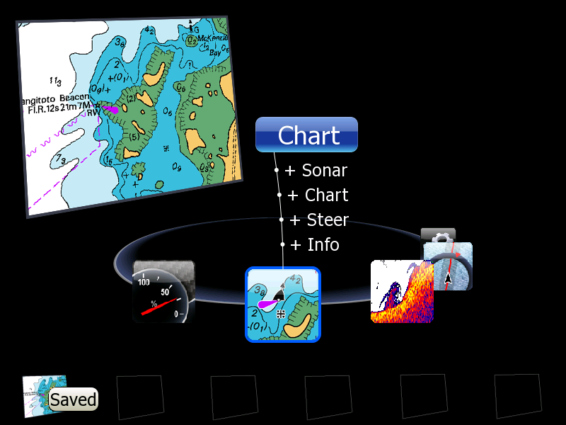
HDS PAGES shortcut saved. The left soft key will now be a shortcut that jumps directly to the CHART page.
Once the all six shortcuts have been created, the HELP message that explains the operation of the shortcuts will never be seen again, as it only appears when a bounding trapezoid area is blank. The settings for all six shortcuts can be deleted by accessing a contextual menu on the PAGES display, as follows:
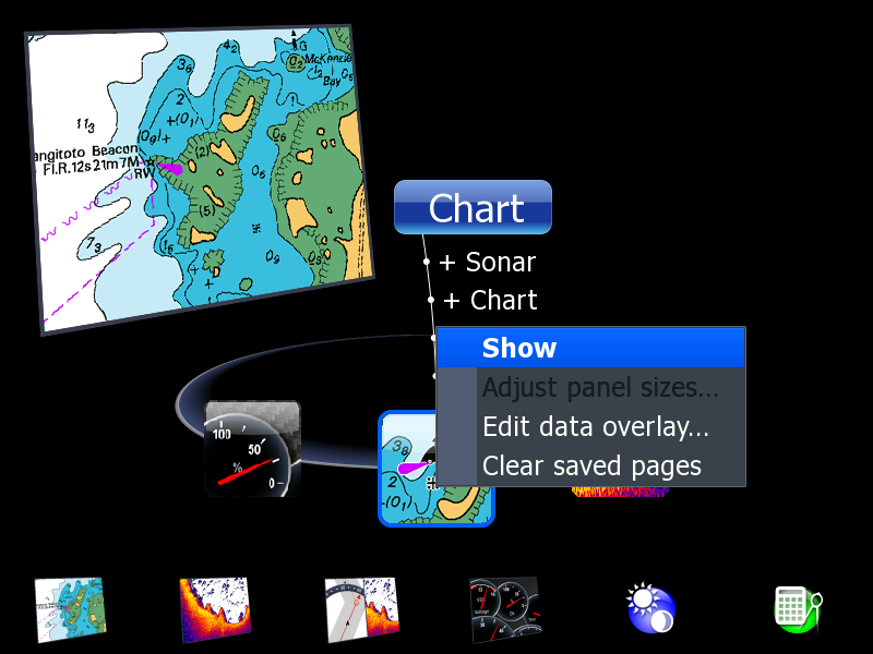
HDS PAGES menu prompt
Cursor to Clear saved pages and hit ENTER. The Clear saved pages meuu appears with prompt Do you want to clear all saved pages? and soft key button choices Yes and No.
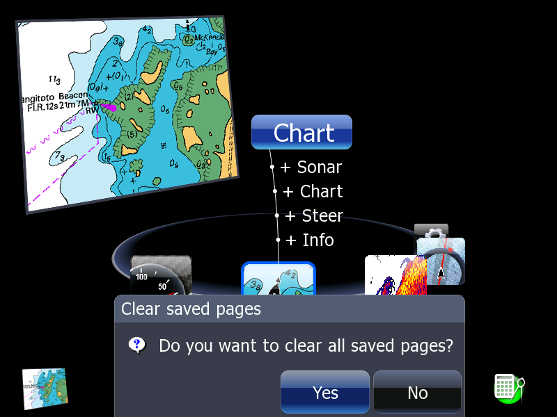
HDS Menu Clear saved pages
If the PAGE hot-button key is held for more than just a momentary press, the mode shifts from the operational mode to the edit mode. If you don't notice this change--and this can easily happen when you are busy at the helm of the boat--the natural inclination is to push the button a second time. Unfortunately, the second button push will then alter the configuration of the hot-button key, making it a short cut to the page that happens to have been selected in the PAGE navigation screen.
The user-interface of the PAGE hot-button keys is hampered by the slow response to user input. When you push a PAGE hot-button key the HDS-8 does not immediately respond with any user feedback. The user is not provided with any response from the HDS that indicates the button has been pushed. It can take several seconds for the screen to change to the new page.
The user can easily be confused by the lack of response to the button push, and the natural reaction is to push the button more distinctly and hold it longer. This leads to the mode change described above. (Also note that if the HELP BALLOON feature is not active, there is little change in the display when the edit mode is entered.) When this happens, the user is again confused because. The change in display presentation may not be immediately noticeable. This leads to another button push, which then alters the programming of the PAGE hot-button that was pushed.
After some time using the feature, the user becomes trained to be patient for any change in the display to occur. The user also becomes trained to not push the PAGE hot-button too long and thus avoids the mode switch problem. However if the user wishes to change the target of a soft key shortcut, the method of holding the soft key button for a long press will accomplish it.
The page has been accessed times.
Copyright © 2012 by James W. Hebert. Unauthorized reproduction prohibited!
This is a verified HTML 4.0 document served to you from continuousWave
URI: http://continuouswave.com
Last modified:
Author: James W. Hebert
This article first appeared February 12, 2012.