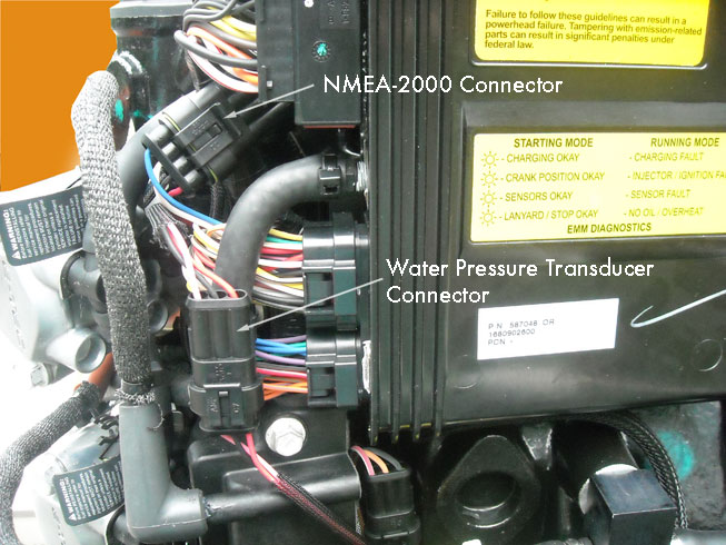
Fig. 1. E-TEC 3.3-liter V6 NMEA-2000 connector and water pressure sensor connector
This article gives an overview of NMEA-2000 networks, details on how to construct them, guidance on connecting a modern outboard engine to a NMEA-2000 network, and general advice on using modern instrumentation to see engine parameters.
Almost all modern outboard engines are certified for connection to a NMEA-2000 network. The only exceptions are Mercury Marine outboard engines. Engines with NMEA-2000 offer the option of using NMEA-2000 networking to display engine data. The Evinrude E-TEC was one of the first, if not the very first, outboard engine to provide this option. Soon Yamaha, Honda, and Suzuki followed. This article will explain in a concise manner the various terms and methods related to using NMEA-2000 networking with modern outboard engines. It will concentrate on the Evinrude E-TEC but will include information of general use to all modern NMEA-2000 outboard engines. The comments about NEMA-2000 wiring are applicable to any engine brand.
The term NMEA-2000 refers to a standard for data transmission on boats that is a product of the National Marine Electronics Association, or NMEA. NMEA have disclosed some details of the standard to the public at no cost on their website. Some vendors have disclosed additional information as part of the instructions for use of their devices. And some experimenters have developed information by observation of the standard in use. Here are some on-line sources of information about NMEA-2000 that may be of interest:
The NMEA-2000 standard specified a method of communication on a network bus. It includes details of the electrical nature of the bus, the manner of sending data, and the format for the data. Such details are not of great concern to the end user, except for details of the bus construction and hardware. Initially in NMEA-2000 there were several different electrical connectors used for wiring the network construction. Over time the marketplace seems to have settled on one choice for network wiring: the DeviceNET Micro connector. This connector is also known by other names, often re-branded by vendors. For example, Lowrance refers to this connector as the LowranceNET Red connector. The present Evinrude wiring appliances use this connector, too.
The initial wiring for a NMEA-2000 network will be to construct a network backbone. To this network backbone various devices can be connected. The various devices will communicate with each other via the network backbone. All devices connect to the network; they do not connect directly to each other.
There are several variations possible in wiring a network backbone, but the most common and most widely used configuration will be as follows:
We can show a simple network in schematic fashion as follows:
TERMINATOR--< <--POWER T--< <---TERMINATOR
                    |
                    ^
                    ^
                    |
                  fuse
                    |
                    |
                To 12-Volt
               Power Source
A network backbone typically has a male-female gender pairing of T-connectors. This means the connectors on the backbone with pins will have power on them. One way to avoid exposing these pins with power on them is to locate the power connector at the end of the backbone. Put a termination on the power node T-connector that has pins. Then the connector that is providing power to the network will be female, and no voltage will be exposed on any downstream connector with pins.
This is a network with nothing attached. To add a device to this network, a Network T is inserted into the backbone:
 TERMINATOR--< <--POWER T--< <--Network T--< <---TERMINATOR
                     |             |
                     ^             ^
                     ^             ^
                     |             |
                   fuse            |
                     |             |
                  To 12-Volt     Device
                 Power Source
The new device connects to a newly added Network T-connector. The device may have its own integral cable, ending in a male connector to attach to the Network T-connector, or the device may only have a Network connector, requiring a drop cable to connect to the network. The network connectors that are mounted on a device are always male connectors, that is, they have exposed pins. A male-female Network Extension cable will connect the device to the Network T-connector. The DEVICE port of the network T-connector will alwasy be female, that is, the connector will have sockets.
A network with only one device is of little use. The device will have no other device to communicate with. The point of the network is to provide communication among all devices. We need another device to make a useful network. To add a second device, a second Network T is added:
TERMINATOR--< <--POWER T--< <--Network T--< <--Network T--< <---TERMINATOR
                    |              |               |
                    ^              ^               ^
                    ^              ^               ^
                    |              |               |
                  fuse             |               |
                    |              |               |
                To 12-Volt      Device          Device
               Power Source
We now have the most basic and simplest useful NMEA-2000 network. Once we are at this point, we can continue to expand the network by adding more devices. One just adds a new Network T-connector to the backbone for each new device, and, if necessary, a Network Extension cable to connect the device to the Network T-connector. Note that the Network T-connectors do not all have to plug-in to each other; a Network Extension cable can be used to extend the network backbone wiring between Network T-connectors as needed.
There are two types of standard connectors, MICRO and MINI, and three types of standard cable, LIGHT, MID, and HEAVY, used in NMEA-2000 network construction.
The most common connector used in small boats is the NMEA MICRO connector. This connector is a DeviceNET Micro-C (also called the DeviceNET Micro-Change) connector. A slightly larger connector can be used for wiring larger networks with longer distances involved; this connector is called the MINI connector. This connector is the DeviceNET Mini-C (also called the DeviceNET Mini-Change) connector. The NMEA MICRO connector is by far the most common connector used in recreational marine products that have NMEA-2000 ports.
The most common cable used in small boats is the NMEA LIGHT cable. This cable uses 22-AWG conductors for the power and has a capacity of 3-Amperes, which will be sufficient for almost any small boat network, and a network backbone of up to 100-meters in length can be used. For longer networks, up to 200-meters in length, MID cable us used, which has 16-AWG power conductors. MID cable used with MICRO connectors permits 4-Amperes of power; MID cable used with MINI connectors permits 8-Amperes. HEAVY cable must use MINI connectors; it has 16-AWG power conductors allows 8-Amperes. All power ratings in Amperes are per segment, so if a split power connector feed is used, the total network power avilable will be doubled.
The most common configuration of cable and connector will be LIGHT cable and a MICRO connector. There is seldom any reason on a small boat to use any other combination.
Although the DeviceNET Micro connector is the recommended standard connector, some brands of marine electronic equipment have developed their own wiring appliances. If you plan to use that brand of equipment exclusively, you may consider using the non-standard wiring appliances for that brand. If you plan to mix brands of equipment, it is better to use the standard wiring appliances for the backbone and to purchase a few special adaptor cables to fit non-standard cables to the network.
The least expensive way to purchase wiring appliances is to buy them in a starter-kit. Simrad sells a "NMEA-2000 Starter Kit" for $70. The kit includes:
The Simrad Starter Kit will create a network with two T-connectors ready to use to connect two devices. Other makers also sell starter kits. You can also buy individual components and assemble your own network wiring devices, but generally this will be more expensive than buying a starter kit. Buying two starter kits may be less expensive than buying one starter kit and a few individual components. If you buy two starter kits you will have a few spare components. (More information about starter kits and their prices is given in a separate article.)
The Network T-connectors made by Lowrance (or Evinrude) and the ones made by Garmin have the standard DeviceNET Micro connectors and are compatible, but, if they are daisy-chained together, the drop cable connectors will fall out of mechanical alignment, that is, the orientation of the connectors in the molded assemblies has not been done on the same angular offset. This can make it difficult to mount a string of Network-T connectors of mixed Garmin and Lowrance brands to a bulkhead. Garmin may be revising their connector orientation to become more compatible with other brands.
The NMEA-2000 network must be powered in order for attached devices to be able to communicate. The network power typically only powers the network interface circuitry on a device. Devices which require a significant power to operate will have their own power circuit which powers the entire device, except for the network interfaces. Some small devices—typically sensors or other very low power consumption devices—will obtain their operating power from the NMEA-2000 network. Because the network interface circuitry is powered by the network power, there will be a constant power drain on the NMEA-2000 network even if a device's own power is switched off. Because of this constant drain, connecting the network power directly to a boat battery is not a good practice. The drain from the network may discharge the battery to exhaustion. A better method of powering the NMEA-2000 network is to provide it with power via a switch. In many cases the IGN or ACCY circuit of the key start switch (which is typically wired with conductors with VIOLET insulation) will be used to power the NMEA-2000 network. This works well if the network is to be operational when the engine ignition key is in the RUN position. If you need the NMEA-2000 network to be operational without having to put the engine ignition key into the RUN position, an alternative source of power should be used. Typically an auxiliary circuit on the boat power distribution and a switch can be used to provide power to the NMEA-2000 network. More sophisticated installation use a combination of either the ignition key switch or a dedicated switch to power the network.
The network voltage is nominally 12-Volts DC, but devices should operate with network power in the 9 to 16-Volt range. Some manufacturers produce devices that can operate with a much as 24-Volts.
Most NMEA-2000 networks on small boats are wired with NMEA-2000 LIGHT cable. The power conductors in NMEA-2000 LIGHT cable are 22-AWG. The network power capacity is rated at 3-Amperes, and a 3-Ampere fuse is typically used in the power cable. The power consumed by any NMEA-2000 device is rated in units of LEN or LOAD EQUIVALENT NUMBER. Every NMEA-2000 device should declare in its specifications its LEN value. A LEN is defined as 0.050-Amperes or any fraction of that. A device that draws 0.049-Amperes is rated LEN=1, and a device that draws 0.051-Amperes is rated LEN=2. The total power on the network with LIGHT cable should be limited to 60-LEN. No single device should consume more than 20-LEN (or 1-Ampere). To assess the electrical load on a network, add up the LEN values of all devices. If a device fails to specify its LEN, you can estimate the LEN value as follows:
In networks with longer backbones it may be necessary to calculate the voltage drop in the network. Voltage drop in LIGHT cable networks will be:
E = 0.1 x LEN x length x 0.057

where length is the total length of the network cabling in METERS
and LEN is the total LEN load of all devices.
For example, in a network with a total load of LEN=10, using LIGHT cable, and a backbone length of 13-meters, the voltage drop will be:
E = 0.1 x 10 x 13 x 0.057
E = 0.74-Volts
For more about network power wiring, the NMEA organization has a good white paper on the topic which should be studied.
It is quite easy to deduce which devices are intended to be powered by the network and which are intended to have dedicated power supplied to them. Devices intended to be powered by the network do not have power cords. Devices which are intended to have their own dedicated power have power cords.
Most Evinrude E-TEC engines have NMEA-2000 support. In model year 2005 and newer, E-TEC engines of 115 to 300-HP have NMEA-2000. In model year 2008 and newer, E-TEC engines of 40 to 300-HP have NMEA-2000. The NMEA-2000 connector on the E-TEC is usually located on a short wiring harness near the EMM. Illustrations below will show the location of the NMEA-2000 connector on various models of Evinrude E-TEC engines.
Fig. 1. E-TEC 3.3-liter V6 NMEA-2000 connector and water pressure sensor connector
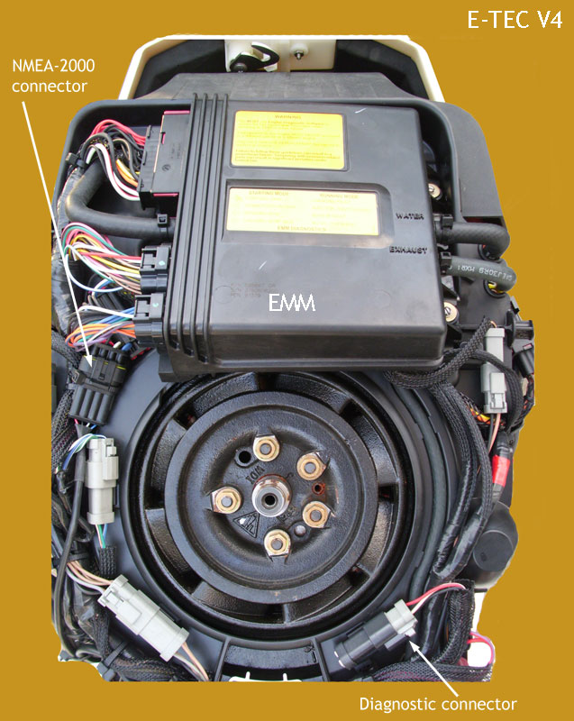
Fig. 2. E-TEC 1.7-liter V4 NMEA-2000 connector and diagnostic port connector. Photo credit: P. Fithian
Fig. 3. E-TEC 1.3-liter I3 NMEA-2000 connector. The sealing plug is still in place. Photo credit: E. Maragos
The connector on the E-TEC is not a standard DeviceNET connector, and a special adaptor cable is needed to connect the E-TEC to the NMEA-2000 network. Both Lowrance and Evinrude sell adaptor cables. The Lowrance Evinrude Engine Cable is PN 000-0120-62; the Evinrude Engine Cable is PN 0764164. Lowrance literature gives more details.
With an Evinrude E-TEC engine connected to a NMEA-2000 network, what data can we expect to obtain? The E-TEC engine sends data in the manner specified by the protocol, that is, in two engine parameter groups. The engine parameter groups have been the subject of much independent study, and some details about them are known. For example, see my own article on NMEA-2000 engine parameter groups.
Since the E-TEC is a two-cycle engine, some of the specified parameters are not applicable and are not sent. The typical engine data available from the E-TEC will be:
Note that data about engine trim is only available from V4 and V6 models. The E-TEC will also send some additional information, not specific to the engine itself:
The E-TEC engine sends this data to the NMEA-2000 network, not to a specific device on the network. Any device on the NMEA-2000 network can receive the data and display the data, if the device has the capability of doing that.
More information on E-TEC rigging for NMEA-2000 is available in a separate article on that topic.
To connect a Honda NMEA-2000 outboard engine to the network you will need a specialized cable. It is Honda part 06653-ZZ3-760HE (formerly part 06328-ZZ3-760HE). This engine cable is generally available from Honda dealers or other sources.
There are many devices available which can display data from a NMEA-2000 network, and there are typically two groups: dedicated instrument displays, and multi-function displays. Examples of dedicated instrument displays for NMEA-2000 data are the Evinrude I-Command gauges, the Evinrude ICON gauges, a number of Evinrude color displays, and the Evinrude NAUTILUS display. (More information about Evinrude branded NMEA-2000 display devices can be found in a forum that concentrates on those devices.)
Almost all modern multi-function displays (such as chart plotters or SONAR-chart plotter combination devices) are certified as NMEA-2000 devices and are ready for connection to a NMEA-2000 network. These modern chart plotter, GPS receiver, and SONAR devices will display NMEA-2000 engine data. A good example of such a device is the Lowrance HDS series. The display device can present the data in various forms, including just the numeric value, in a dial-pointer gauge representation, in grow-bar graphs, and in other clever manners.
Among the popular modern multi-function display device, the Humminbird devices are notable because they are not NMEA-2000 device. However, Humminbird has created a gateway to NMEA-2000 will will permit their devices to interoperate with data from a NMEA-2000 network. More details are given in a separate article. (Since this article was written, Humminbird has introduced newer models of their display devices which have NMEA-2000 interfaces.)
It is very common that NMEA-2000 instrumentation has the ability to add functionality to the data from the E-TEC engine. For example, an instrument can monitor the fuel flow rate of the E-TEC over time, and compute the volume of fuel that has been used. The instrument can accumulate the fuel volume used and deduct that volume from another value for current fuel tank volume. In this way the instrument can compute the fuel tank level. (For more about calculating fuel tank level with the indirect method see my separate article.) All of these calculations take place in the instrument, not in the E-TEC engine itself. A cleverly designed instrument can retain fuel volume data in memory and track the total fuel consumption over various time periods, as in during a particular trip or over an entire season. Again, these calculations are performed by the instrument and the data stored somewhere on the network, either in the instrument itself or in a dedicated data storage device.
It is very common that a Global Navigation Satellite System (GNSS) receiver will be attached to the NMEA-2000 network. From the GNSS, data about boat speed over ground can be obtained. A cleverly designed instrument or multi-function display device can then use the boat speed data and the fuel flow data to compute the instantaneous fuel economy in miles per gallon (or other units). The instrument can also accumulate and remember distances travelled, providing a log of distance over various time periods, such as by day, by trip, or by season.
In the specific case of the Evinrude I-Command gauges, the gauges themselves do not have any memory or data storage capacity. In order for the gauges to provide functions like fuel volume used over time, a special data storage device must be added. Lowrance calls their storage device the EP-85R (details are available in the instruction manual); the EP-85R is available for $80. At initial view, the retention of certain stored data in a separate module may seem awkward, but it does have an advantage. The data may be accessed by more than one I-Command, Lowrance gauge, or Lowrance multi-function display, and the data can be used for display on several devices.
For information on how to set-up, configure, and operate a particular NMEA-2000 display device, including the added functions such as fuel tank level computation, season fuel usage, trip fuel usage, and so on, please consult the owner's manual for the particular device. NMEA-2000 instruments and display devices are complex in nature, and in order to become familiar with their operation it will be necessary to carefully read and study their operating instructions and literature. This article cannot possibly hope to explain how to operate all NMEA-2000 display devices.
In general one will notice a very strong similarity between the Evinrude branded I-Command gauges and the Lowrance LMF-series. It is widely known that Lowrance manufactures the I-Command gauges for Evinrude. However, the gauges are not identical. In the Evinrude I-Command gauges there is added functionality. The I-Command gauges can be used to initiate the E-TEC winterization process (V6 and V4 only). It is also believed that I-Command gauges will display certain engine diagnostic messages that are proprietary to the E-TEC which may not be available on generic gauges. For this reason it is often recommended to have at least one Evinrude-branded I-Command gauge (or ICON Pro RPM gauge) on a NMEA-2000 network in conjunction with an E-TEC outboard engine.
In selecting an Evinrude-branded NMEA-2000 gauge, one has the choice of I-Command or ICON Pro series gauges. The I-Command gauges have been available for many years and are well-known. The ICON gauges are new products from Evinrude and are not as well-known. In general, all features of I-Command gauges are available on ICON Pro-series gauges, and ICON Pro series adds some new features. A comparison between the two shows the following advantages for ICON Pro series:
This is an advantage for the ICON Pro series. With the I-Command system you need external devices to accomplish all of those functions.
This is an advantage to ICON Pro series compared to I-Command. You can adjust the trim calibration, you do not need a memory module for fuel volume used, and you do not need a network-T and drop cable for each gauge.
It is frequently seen that when converting to NMEA-2000 instrumentation there will be a problem in the TRIM data resulting from a simple electrical wiring problem. To have a TRIM indication the trim sensor in the engine mounting bracket must be supplied with voltage and current. When a conventional trim gauge is used the voltage and current are supplied through the conventional trim gauge. The E-TEC EMM will work in parallel with the conventional gauge and read the voltage from the sensor.
If there is no conventional gauge, the trim sensor must be supplied with voltage and current by some other means. In the OEM wiring harness for I-Command there is a provision for providing voltage and current to the sensor. (The provision is a 47-ohm 5-watt resistor connected from the VIOLET or switched 12-Volt circuit to the trim sensor circuit, the WHITE with TAN stripe circuit.) Some owners who don't have the specific wiring harness have adapted their existing wiring harness to do the same by adding the 47-ohm 5-watt resistor to it. I don't see any difference electrically between the OEM harness and making your own adaptation; just be certain to protect the circuit from contacting other circuits or ground. On E-TEC engines with ICON controls, the trim sensor will be connected to the ICON control module, and no other wiring is necessary for operation of the TRIM circuit.
Once the trim sensor has power and voltage applied, the output of the sensor will be sending a signal to the EMM that represents the position of the engine or its TRIM.
The second element of the display of TRIM on a NMEA-2000 gauge is the calibration of the signal. The EMM gets a voltage from the sensor. The EMM converts this voltage into a digital signal that represents the engine position. In each installation there may be variation in the range of motion provided in the engine trim. For example, there is usually a mechanical limit for the downward trim. Since this varies, the EMM provides a calibration method by which you can set the lowest position of the engine to be a reading of "000" and the highest position of the sensor (in the trim range, not the fully tilted up range) to be a reading of "100". This is accomplished in the Evinrude Diagnostic Software. The EMM can be taught to learn the two voltage limits of the the signal from the trim sensor. After this calibration the EMM sends a digital signal in the range of 000 to 100 representing the engine trim position. If you did not perform the calibration, the EMM may not send a TRIM signal.
As I just described, I believe that you must perform the calibration to get the TRIM signal on the NMEA-2000 network, but I cannot say that with certainty. On my installation I had a working TRIM signal before I did the calibration procedure. It was just that the lowest reading was some other value higher than "000" and the highest reading was some other value lower than "100". It could be that this occurred because my dealer previously set this up. I don't know if the TRIM signal is present on an E-TEC just "out of the box" but not calibrated to the individual installation. This might also very with EMM software versions. Further investigation into this question is underway.
I recommend reading all (20) of the additional resources hyper-linked in the article above. In a separate article I describe in detail the installation of a Lowrance HDS-8 multi-function chart plotter and the connection of it to the NMEA-2000 network. In another article I describe in detail the ICON gauges. These two lengthy articles are also recommended for readers who seek further information on NMEA-2000 and E-TEC instrumentation.
Further information specific to Evinrude can be found in the SMALL BOAT ELECTRICAL forum in the topic group EVINRUDE I-COMMAND, ICON Pro, ICON Touch.
continuousWave --> Whaler --> Reference
Copyright © 2012 by James W. Hebert. Unauthorized reproduction prohibited!
This is a verified HTML 4.01 document served to you from continuousWave
Author: James W. Hebert
This article first appeared August 25, 2012.
