This article presents recommendations for small boat 12-Volt direct-current (DC) electrical circuits and how they should be wired and installed. Electrical 12-Volt DC circuits on a small boat can be considered in three segments: primary power distribution, secondary power distribution, and branch circuits.
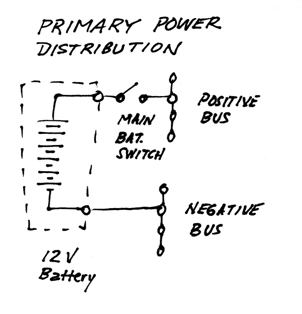
The source of electrical power on a boat is a storage battery, usually a lead-acid storage battery. Typically a single 12-Volt battery is used on a small boat. On larger boats the 12-Volt power may be provided by more than one battery. In some cases 6-Volt batteries are arranged in series. This is done because the size and weight of a 12-Volt battery would be too large and heavy. However, for most small boats, a 12-Volt battery can be used. There may also be more than one 12-Volt battery, but in most cases they are not operated in parallel. If there is more than one battery available, there generally is a switching arrangement which allows selection of which battery will be used, or if the batteries will be operated in parallel.
The battery negative terminal is connected to the primary negative distribution bus. On a small boat, the terminal of the battery itself is sometimes used as the primary negative distribution bus. This requires more than one connector to be placed on a binding post, which is not a good practice, particularly in an environment like a small boat where there is likely to be vibration. However, it is often done. Aggregating two or three connectors under the negative terminal of the battery is a common installation technique.
The battery positive terminal is typically connected to the main battery switch. This portion of the circuit is typically not fused because of the high current which must flow on it during engine starting. For this reason, the wiring from the battery positive terminal to the main battery switch should be kept as short as possible. Because a heavy conductor is generally used, often of size 4-AWG or larger, the cable will have sufficient strength and insulation that it does not need to be protected, however, in many installations a flexible plastic cable conduit is used.
The main battery switch provides a mechanical and electrical disconnect of the battery from the rest of the boat's electrical system. When the main battery switch is in the OFF position, electrical power to the rest of the boat will be removed. The output of the main battery switch is connected to the primary positive distribution bus. On a small boat, the terminal of the switch itself is often used as the primary positive distribution bus, and two or three conductors may be connected to it under one terminal post. Again, this is not the recommended practice, but it is often done.
The wiring used in the primary power distribution should be sized so that it can handle the maximum current needed, which typically is the engine starting current. The wire must also be sized so that the voltage drop in the total circuit is not excessive at the maximum current load. In a 12-Volt direct current circuit, the voltage drop consideration will generally force the use of a wire conductor whose size is greater than that needed for the current alone.
The main battery switch may also be of a special design which permits connection of two batteries. Such switches typically have a special contact arrangement which provides for setting the power to OFF, to be sourced from either battery, or to be sourced from both batteries in parallel. Many arrangements of dual batteries and primary power distribution switching are possible.
The only loads connected to the primary power distribution are feeds to secondary power distribution centers and the engine starting circuit.
Color coding of the conductors in the primary power distribution should follow the standard wiring practice:
Positive = RED
Negative = YELLOW or BLACK
Traditionally BLACK insulation was used for negative conductors in DC wiring, but recently YELLOW has become the recommended standard color in order to distinguish the DC wiring from any AC wiring on the boat. Since in a small boat there is likely to not be any permanently installed AC wiring, BLACK insulation for negative DC conductors is often still used.
If the wire insulation cannot be easily color coded, the ends of the wires should be clearly identified with color coding using a color marking identifier such as color vinyl electrical tape or color heat shrink tubing. Proper identification of the polarity of conductors is extremely important. Do not rely on memory or intuition to enable identification of cables.
The primary battery distribution circuit is generally not protected by a circuit breaker. While this seems at odds with the general rule of electrical power distribution, the reasons for omitting the circuit breaker have to do with practical problems.
In theory, a circuit breaker in the primary battery distribution would need to be sized to handle the engine cranking current. At the initial start of the engine electrical starter motor, the current flow is nearly as great as in the case of a short circuit. The instantaneous current flow is probably several hundred amperes. Once the engine starter motor starts to spin the engine, the current drawn reduces, but it is still in the region of 100-amperes. A circuit breaker would need to be capable of tolerating these conditions without tripping, yet be able to trip if a sustained short circuit occurred.
In practice, a circuit breaker in the primary battery distribution would need to have a very low internal resistance. Any resistance in the circuit breaker itself will create undesired voltage drop across the circuit breaker. At engine cranking it is crucial that the primary power distribution deliver as much voltage as possible to the electrical cranking motor, and any voltage lost in the distribution circuit will have the effect of reducing the cranking speed. Another practical problem with a very-high-current circuit breaker is its size. A circuit breaker capable of handling a current of several hundred amperes will necessarily be physically large, if only to accommodate the terminal posts needed to connect to it. A third problem is cost. Such circuit breakers will be expensive.
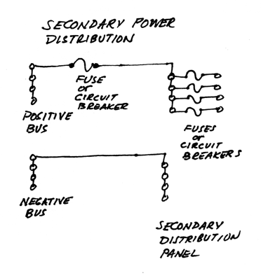
Secondary power distribution circuits connect to the primary positive and negative buses. A current protection device, typically a resettable circuit breaker but sometimes a fuse, is placed in the positive circuit to protect against over-current conditions. The conductors must again be properly sized for current capacity and voltage drop. Because the length of the conductors will be much longer than in the primary distribution, attention to voltage drop is important. The current capacity of the secondary distribution conductors must be able to handle the aggregate current of all the loads attached, and to provide power without excessive voltage drop at that current load.
Color coding of the conductors in the secondary power distribution should follow the standard wiring practice:
Positive = RED
Negative = YELLOW or BLACK
Secondary power distribution is best accomplished by use of wiring accessories such as marine power panels or load centers. A power panel will typically have two power buses, one for positive and one for negative. The panel will also have several circuit breakers or fuses pre-wired to the positive bus.
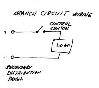
Branch Circuits are wired to the secondary power distribution panels. If a control element such as a switch is needed, it is placed in the positive circuit. Some devices have their own ON-OFF control and do not need an additional one for the brach circuit.
Color coding of the conductors in branch circuits should follow the standard wire color codes as follows:
Positive = color according to circuit function, see below,
           or RED
Negative = YELLOW, BLACK, or BLACK plus color
           according to circuit function
A short list of common circuit functions likely to be found in a small boat and their associated colors for the positive conductor is
BLUE = instrument lamps or cabin lamps
VIOLET = accessories operating from engine ignition key switch
GRAY = navigation lamps
For example, the circuit for the boat navigation lamps should be wired with the positive conductor having GRAY insulation and the negative conductor having a BLACK with GRAY stripe. A separate article has a complete listing of color codes recommended. If the negative conductor wire color cannot easily be obtained, use BLACK insulated wire and identify the ends with a small marker of the appropriate color using vinyl electrical tape or color heat shrink tubing. If the recommended color is not available for the positive circuit, use wire with RED insulation. A more comprehensive list of color codes for wiring is given in a separate article.
Several loads may be aggregated on one branch circuit if the total current demand is small. Again, while not recommended, it is a common practice that more than one connection be made to a terminal, and two or three loads may be wired to the fuse or circuit breaker output on the electrical panel.
Wiring of conductors to terminal posts should be done with ring terminal lugs. The ring terminal should be properly sized for the terminal post it will be used under. If possible, avoid aggregating more than one connector on a terminal post. Electrical bus terminals often use a special fastener, the binder head screw. These help to make good electrical connection. If terminal posts are provided with washers, particularly star washers, be certain to use them. They help provide better mechanical and electrical connection.
The physical size of electrical conductors for any boat power distribution circuit must be selected to be large enough to carry the electrical power without too much voltage drop or heating of the conductor itself. Selection of conductor size for distribution of 12-Volt power must always be done with consideration of voltage drop, as generally the voltage drop factor will always require a conductor of larger size than necessary for handling the current alone. A simpe method for selecting proper conductor size is presented in a separate article, "Conductor Size for Power Distribution." Note that for reasons of compliance with general recommendations, no electrical conductor should be smaller than 16-AWG unless part of a multi-conductor cable.
DISCLAIMER: This information is believed to be accurate but there is no guarantee. We do our best!
Copyright © 2009 by James W. Hebert. Unauthorized reproduction prohibited!
This article first appeared September 13, 2009.
This is a verified HTML 4.0 document served to you from continuousWave
Author: James W. Hebert
