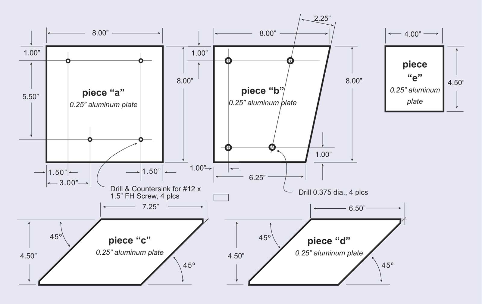
Five pieces are needed to form the bracket, cut from 0.250-inch aluminum plate. Use 6061-T651 or similar aluminum stock.
Drawing Credit: John Anderson
This article shows in detail how to construct an offset auxiliary engine bracket for use with the Boston Whaler 15-foot hull. The unusual shape of the 15-foot hull transom necesitates this special offset bracket. This bracket was designed and fabricated by John Anderson, who also supplied all the drawings and photographs incorporated in this article. It is based on the original "pony bracket" offered by Boston Whaler, unfortunately no longer available.
I am always impressed with the astonishingly high standards of workmanship that are typically found in modifications to classic Boston Whaler boats, and John's results are impressive, indeed. John's design has given careful consideration to many requirements, including clearance of existing objects on the transom, motor height, and location of reinforcing wood in the hull. This well thought out design and beautifully constructed bracket should provide valuable guidance to anyone planning to install an auxiliary motor on a 15-foot hull. Bravo, John!
John writes:
"Since the "pony" bracket for the classic 15 is no longer available from Boston Whaler, I decided to fabricate one based on the drawing in the Reference Section. But the first obstacle was I didn't have easy access to the aluminum extrusion indicated. Second and more importantly, there are no dimensions on the drawing (it appears to be an assembly or installation drawing). So, I started from scratch and generated a new design based on the 0.250-inch aluminum plate that I had available. I cut the pieces to size and had a neighbor do the welding for me. The images (below) show the result. My dimensioned drawings (also below) are provided so this part could be exactly duplicated by anyone else. Note that the 6-HP Yamaha kicker is a short shaft. Because of the "V" in the 15 hull, the cavitation plate can be higher than the main motor and still be properly immersed at sub-planing speeds."
|
|
|
Aluminum Components Five pieces are needed to form the bracket, cut from 0.250-inch aluminum plate. Use 6061-T651 or similar aluminum stock. Drawing Credit: John Anderson |
 |
|
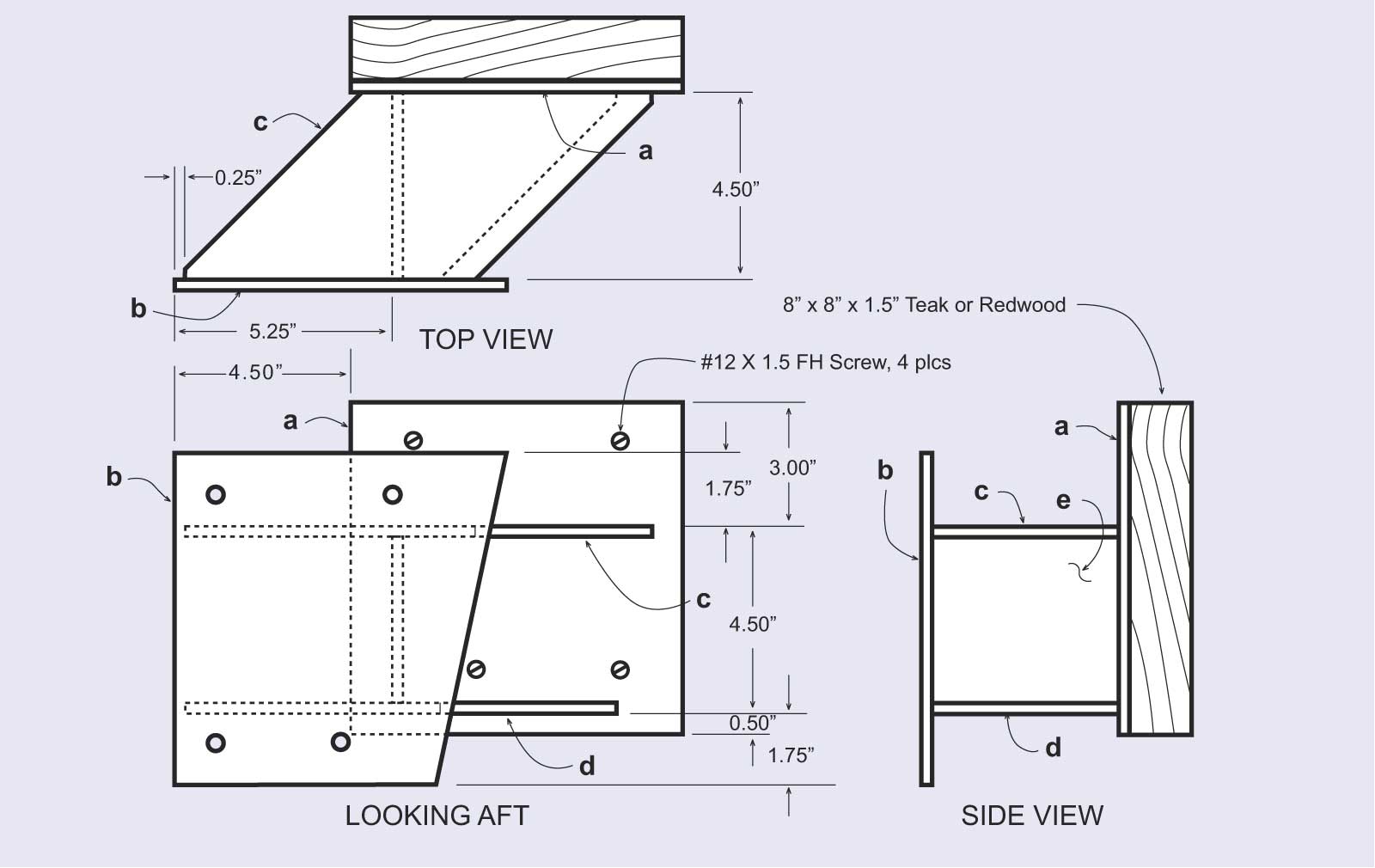
Assemby Details The five pieces are welded together to form the bracket shown. Drawing Credit: John Anderson |
 |
|
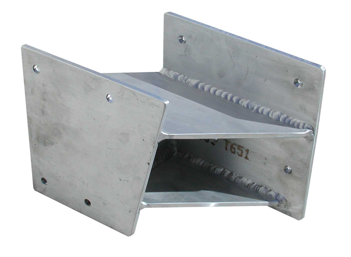
Welded Assembly The welded assembly shown prior to finishing and addition of the wood engine mounting spacer. Photo Credit: John Anderson |
 |
|
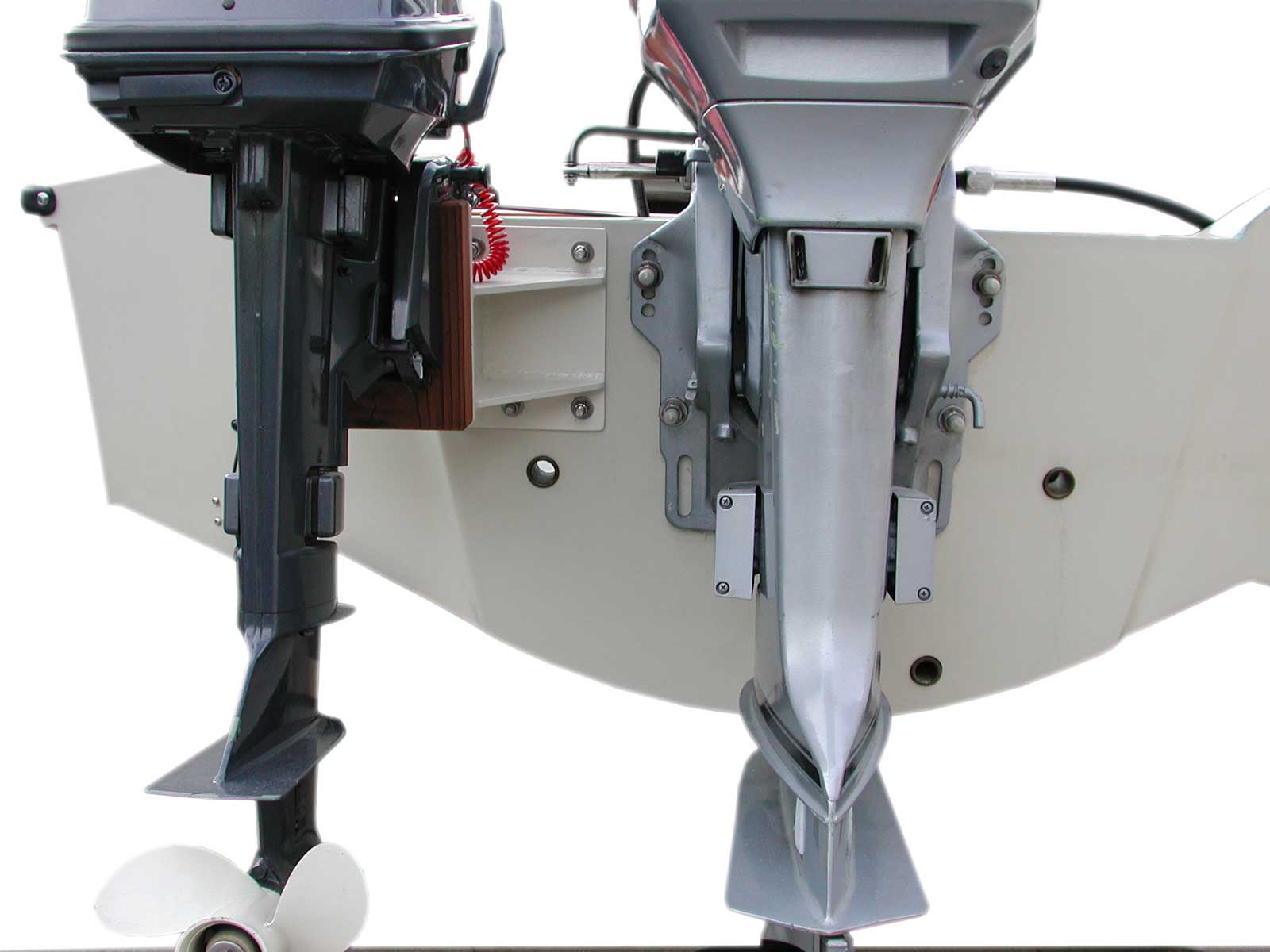
Installed Bracket Stern View Four holes are drilled in the transom (in the area reinforced with embedded wood), and the bracket secured as shown. The bracket has been very well designed so as not to interfere with the drain locations. The hole layout has been chosen to provide mounting points that are clear of interference from interior parts of the splash well. Also note some details of the main engine mounting. The limited depth of the engine splash well has caused the lower mounting holes on the engine to be too deep for use in this application, and the lower mounting bolt has been located in a new hole, drilled higher in the bracket. This allows the lower mounting bolt to clear the bottom of the splash well, but further adjustment of the engine mounting height cannot be accomplished. The engine is mounted "one hole up" in the upper mounting holes, the usually recommended position on many Boston Whaler boat transoms. Photo Credit: John Anderson |
 |
|
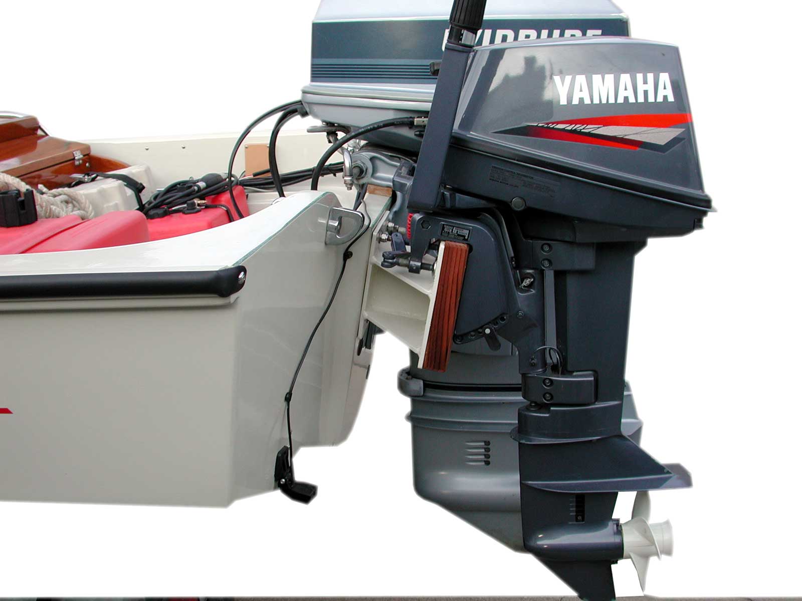
Installed Bracket Side View A side view of the bracket installed on a Boston Whaler SPORT-15. Countersunk screws attach the wood to the bracket, keeping the mounting surface clear. The mounting toggles for the auxiliary engine look like they just clear the bracket. A thicker wooden piece on the bracket would take care of any interference problems with different engines. The 6-HP Yamaha engine shown is a "short shaft" model (15-inch leg). Photo Credit: John Anderson |
You can reproduce the two drawings seen above for your own personal, non-commercial use. The source files contain JPEG format images that are twice the size seen displayed here. Use your browser to transfer (via HTML) the drawing files to your local storage volume. The precise method depends on the operating system and browser being used.
This article owes its very existance to the wonderful design, drafting, fabrication, installation, and photography of John Anderson. I am certain all readers appreciate the contribution and the fine workmanship it documents.
If you have a comment or question about this article, please post it to the linked message thread in the REPAIRS/MODS forum.
DISCLAIMER: This information is believed to be accurate but there is no guarantee. We do our best!
The page has been accessed times.
Portions Copyright © 2003 by James W. Hebert. Unauthorized reproduction prohibited!
This is a verified HTML 4.0 document served to you from continuousWave
URI: http://continuouswave.com
Last modified:
Author: HTML version by James W. Hebert from material supplied by John Anderson.
This article first appeared September 28, 2003.