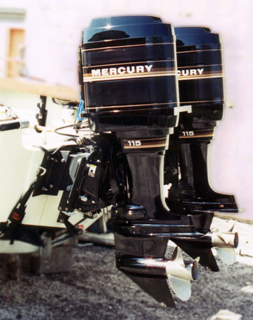
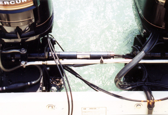
Twin Mercury 115-HP engines are mounted on 10-inch setback brackets on the original standard transom of this Whaler 18-Outrage.
PhotoCredit: LHG - Scan: JWH
(Author's note: If you have not already done so, you will want to read the companion article on Engine Setback Brackets which explains the many reasons for their use.--jimh)
By far the most common hull configuration on Boston Whaler boats is one where the transom has been notched to produce a mounting point appropriate for outboard motors with the usual engine shaft lengths of 20 or 25 inches. This is generally referred to as a notched transom or standard transom. Although not specifically designed for it, the standard transom can be used with engine setback brackets. Even setbacks as long as 30-inches have been added to standard transom boats. Shorter engine brackets, in the 6-12 inch range, are more likely choices for installation on a standard transom.
This article shows some details of the installation of a Springfield Marine 10-inch engine setback bracket on a Boston Whaler 18-Outrage with a standard transom as accomplished with great success by Larry Goltz.
Although these particular brackets are no longer in production, there are similar devices available in the current marketplace. (See the listing below.) Larry's installation has been done with great care and attention to detail, and study of it will provide many ideas for your own installations.
In addition to the bracket installation, the article also shows the use of hydraulic steering, an upgrade frequently required when engines are mounted on brackets. The novel design of the hydraulic steering system offers improvement over the usual installations and will be explained in detail.
This installation has been made on a 1986 Boston Whaler 18-Outrage. The engines are twin (1984 and 1985) Mercury 115-HP outboards with the standard long shaft (20 inches). These engines do not have oil-injection and must use pre-mixed fuel, but this is an advantage in this installation because there are no extra oil tanks or oil lines to be accommodated in the installation. Although this is a twin engine installation, everything shown is equally applicable to single engine installations.
The brackets were made by the Springfield Marine company, but in 1999 they had the misfortune of a very intense fire at their plant. The tooling that was used to fabricate these brackets was destroyed. After recovering from the fire they no longer have the brackets in their product line. Some large catalogue suppliers like Cabelas may still have a limited selection of these brackets available in their warehouse. At one time these brackets were made in 6-inch, 10-inch, and 12-inch setback lengths. They were selected because they:
The amount of setback in this case was limited to 10-inches because of constraints in the length of the storage space available for this particular boat.
The original engine mounting holes in the transom, if properly located , should have been drilled so that the engine's mount sat on the transom's top when using the top sets of holes of the engine's mount plate. If this is the case, then the setback bracket can make use of the existing mounting holes. If the existing holes are drilled higher in the transom, they may be too high to accommodate the bracket. In the case of the Springfield bracket, the lowest setting of the bracket adds about an inch of height to the ultimate engine mounting height even in the full-down position. Mounting the bracket in the existing holes is much preferred, as it eliminates having to plug and re-glass the old holes.
When fitting the brackets to the transom, it is advisable to use new stainless steel mounting bolts. Typically 1/2-inch diameter bolts are used. Use of fine-thread bolts is suggested, as the usual coarse thread (1/2 x 13) seems prone to problems with galling. Application of anti-seize compound may help. (This problem is under discussion in the forum.)Use of vibration resistant nuts (Ny-Loks) or double nuts is also suggested. The lower bolts and nuts will be submerged when the boat is at rest, and they should be protected against galvanic corrosion with sacrificial cap nuts.
In twin engine installations, the location of the original mounting holes may cause the factory installed Towing Eyes on the transom to interfere slightly with the bracket. In some cases it may be necessary to file a small relief in the bracket to provide clearance for the tow eyes. Relocating the tow eyes would be a major inconvenience.
Since there is considerable lift available in most brackets, it would seem that mounting the engine to the bracket should be done at the top set of holes, i.e., the holes which produce the lowest engine mounting. In this installation, however, the engines have been mounted one hole up to create space between the engine and the bracket. This space will be used to route cables across between the two engines in this twin installation. This technique may not be applicable to all installations.
In deciding which set of holes to use on the engine mounts, an additional consideration is the clearance needed for the steering gear. If hydraulic steering by a center actuator is used, check carefully for proper clearance when the engine is tilted to the full up position. If mechanical cable steering is used, this will not be a problem, nor should it be a problem with side-mounted hydraulic actuators. (More on this later.)
When the vertical adjustment of the brackets has been set to the fully down position, the brackets still create about one inch lift of the engine mounting height because of their sloped design. Depending on the type of propellers used, more increase in lift can be tolerated. In this installation, when "performance" props are used the brackets are cranked up 1.5-inches. When standard props are used, the brackets are lowered to their deepest setting (which due to the mounting still provides about 2-inches of lift from the standard position.)
In the case of the Springfield bracket, vertical lift is adjusted by turning a large jack screw captivated in the bracket. (This jack screw is not seen in the photographs.) Adjustment is made with a ratchet or other wrench from below and cannot be done while underway. If you want vertical adjustment while the boat is underway you will have to invest in a more expensive and complex hydraulic cylinder lift bracket with remotely controlled actuator.
By combination of hole choice and the 4-inch lift available from the bracket, extra-long shaft engines (25-inch) can be mounted on transoms designed for 20-inch engine shafts. Elevated mounting like that can be desirable because it moves the engine power head farther above the water.
|
|
Springfield Marine Setback Bracket Twin Mercury 115-HP engines are mounted on 10-inch setback brackets on the original standard transom of this Whaler 18-Outrage. PhotoCredit: LHG - Scan: JWH |
The brackets shown are finished in a black powder coat, which looks nice with the black Mercury engines, but the manufacturer later switched to a silver anodized finish which may actually look and wear even better. Portions of the brackets will be immersed so it is important to protect the aluminum from corrosion, particularly in salt water. The lower mounting bolts of both the bracket and the engine are fitted with Mercury aluminum anode cap nuts to prevent galvanic corrosion. The tilt tube of the port engine (foreground) has been capped with a 5/8-inch bailer plug to prevent ingress of water and dirt. Because of the hydraulic steering arrangement (to be explained later) this tube is not used.
 |
|
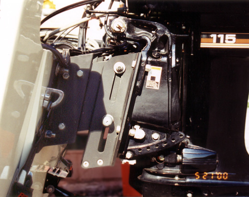
Setback Bracket Detail Shown in the fully down position, about 4-inches of lift is available in the adjustment slots. The bracket mounts to the transom using the original engine mounting holes. PhotoCredit: LHG - Scan: JWH |
Besides the performance gains from the bracket, this installation has a secondary goal of eliminating clutter from the boat's engine well. All cables to the engines have been rigged so as to keep them out of the engine well. The hydraulic hoses for steering, the mechanical cables for throttle and shift, the electrical cables for engines controls, and finally the fuel line hoses have all been routed along the starboard side of the well to the starboard engine, then across to the port engine, in some cases by spanning the gap between the engines. The side-mounted hydraulic steering cylinder is used as a support for the cable span between the engines. The end result is a very clutter-free engine well.
The batteries have been moved in the well so that they have their long dimension running fore-and-aft, creating the maximum amount of open space in the center of the motor well. Wiring from the battery to the engine is kept outboard and sternward. The electrical set up on this boat is kept as simple as possible. Each engine is connected to its own battery. There are no elaborate battery switching and interconnections, which eliminates the need for large electrical cables to cross the engine well. Electrical load of accessories like bilge pumps, VHF radios, SONAR units, etc., is divided between the two batteries. A set of jumper cables is used to interconnect the batteries when needed.
Because of the shift in engine weight aft, it is very likely that the drain holes of the motor well will now be below waterline when the boat is at rest. This will cause flooding of the engine well. To prevent this, rubber drain plugs are used to block the engine well drains. These can be removed if necessary to help clear water from the engine well when underway. The drain holes are typically 1-1/4 inch inside diameter.
To remove water that might accumulate in the engine well, a small pump is rigged at the center of the engine well sump. This pump operates on demand from a float switch. The pump is wired directly to one of the batteries in the well compartment. The pump exhaust is directed over the transom. This pump arrangement keeps the well dry in normal operation. If the boat were to become swamped, the pump to fail, or the battery to become discharged, the drain plugs can be removed to restore self-draining.
The aft shift in engine weight will not only affect the boat trim when in the water but the weight distribution on the trailer as well. When adding a bracket to a trailered boat, check the weight distribution on the trailer after the bracket has been added. There will be a reduction in tongue weight (from the shift of the engine weight to farther behind the axles). It may be necessary to reposition the boat relative to the axle(s) to restore proper tongue weight.
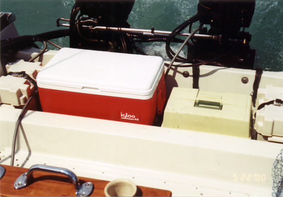
With the engines and their cables gone, the transom well becomes a very handy open storage locker. To protect the gel coat from scratches, "Dri-Dek" has been installed under the battery cases and in the area where coolers, etc., will be stored. By selecting coolers and containers that fit nicely into the well, you can move many stored items from other cockpit locations to the engine well locker. The notion of organizing equipment into removable carry-on cases really has some advantages, too, particularly in a small trailerable boat. You can pack and organize your gear at home, then carry it down to the boat and toss it aboard. This allows for very rapid deployment of the boat once it hits the water. This technique also makes preparing the boat for storage much easier, by reducing the amount of "remove ables" like dock lines, bumpers, and other gear left on the boat while on the trailer or in unsecured storage. You can also have different coolers/lockers packed with different gear, say one with fishing equipment and one with overnight gear. With some ingenuity the cooler/locker can easily be secured with hold-down straps or bungie cords in the engine well.
 |
|
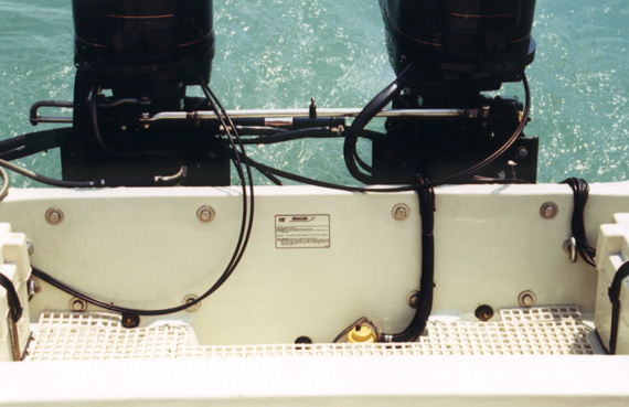
Transom Well Without the engine and cables, the empty well gives back valuable space to the boat's interior. PhotoCredit: LHG - Scan: JWH |
 |
|
Storage Well Here is the well with gear loaded for fishing. PhotoCredit: LHG - Scan: JWH |
Overlooked so far in the discussion has been the issue of how to accomplish steering when the engines are mounted on large setback brackets. The most common solution is to upgrade to hydraulically operated steering, as mechanical cable steering rigs will probably be unwieldy and work poorly. Hydraulic steering itself offers many compelling features, but with engine setback brackets it becomes almost mandatory.
Most conventional cable steering is accomplished using the tilt-tube of the engine. The tilt-tube is the hollow tube, bolted to the the non-moving portion of the engine's mounting bracket, that forms the axle on which the engine rotates and tilts upward. Locating the steering actuator on the axis of tilt is advantageous because as the engine is tilted up, the steering linkage will rotate with it. This type of steering gear needs the least amount of clearance in front of the engine to allow a full range of tilt.
In cable steering mechanism installations, the actuator for the cable steering is threaded onto the starboard end of the tilt tube. The actuator extends through the tilt tube and its steering arm exits at the port end of the tilt tube, where a drag link is used to couple it to the engine tiller extension to affect steering of the boat. Because of tradition, the helm position is almost always on the starboard side of a boat (if not on centerline), and thus is practically universal that an ouboard engine have a tilt tube that is rigged to receive the steering mechanism by attachment to the starboard end of the tilt tube.
In hydraulic systems, there are two approaches, the center actuator and the side mounted actuator. The center actuator is more common, particularly when used with single engines.
In the center actuator style of hydraulic steering, movement of the steering wheel causes an hydraulic cylinder to slide back and forth along a mounting rod. The moving cylinder is connected to the engine tiller extension; the mounting rod is made stationary by linking its ends to new, special links that fasten to (and bolt through) the tilt tube mechanism on both ends. The hydraulic control lines connect to the actuator, and they must have slack and range of movement enough to follow the hydraulic cylinder as it slides left and right along the mounting rod.
The appeal of this configuration is that the amount of hydraulic fluid required to move the actuator rod is the same in either directions. This factor is important if autopilots are to be interfaced with the hydraulic steering. The disadvantage of this style actuator is that it takes up quite a bit of room in front of the engine and may affect the amount of tilt that is possible, depending on the engine well depth and space.
In the side mounted style of hydraulic steering, the hydraulic cylinder is fixed in its position, and movement of the steering wheel causes the associated actuator rod to move in or out of the cylinder. The cylinder is normally threaded on to the starbarod end of the tilt-tube hole, and the actuator rod passes through the tilt tube, exits the port end, and is connected by a drag link back to the engine tiller extension, just as is done in the case of mechanical cable steering actuators. Side mounting hydraulic actuators of this type cost approximately $150 less than the balanced type actuator. They also offer the advantage of needing less space under the engine to allow room for tilting. Since the cylinder is fixed in position, the hydraulic cables that attach to it do not need to have slack in order to travel with the cylinder. This eliminates on pair of cables from the engine well area that have to move as the engine moves in steering.
A side mounted hydraulic cylinder is said to be asymmetrical or unbalanced because the volume of hydraulic fluid that is needed to move the actuator is different for the two directions of travel. When the actuator rod is moved out of the cylinder housing, more fluid is needed than when the actuator rod is moved into the housing. This asymmetry makes it unsuitable for use with autopilots that require a balanced hydraulic cylinder. The helm pump produces a certain amount of fluid output for each turn of the steering wheel. With the side mount cylinder, more turns of the wheel will be required in the direction of moving the actuator rod out of the cylinder than will be needed to move the rod back into the cylinder. A typical side mount actuator will have 5.7-turns lock-to-lock in one direction (pushing rod out of cylinder) and 4.7-turns lock-to-lock in the opposite direction (pulling rod back into cylinder). Since the amount of rod movement will be the same, the force needed to turn the steering wheel will be less in the direction with the greater number of turns, that is, when pushing the rod out of the cylinder.
The exact nature of the tilt tube varies a bit from engine to engine. In general most all engines have their tilt tubes installed at the factory so that they are rigged for mounting of the steering equipment (either mechanical cable or hydraulic) to the starboard end of the tilt tube. This stems from the usual location of the steering on the starboard side of the boat and the routing of the steering cables on the starboard gunwales. On some engines the tilt tube will similarly threaded on the port end, and could accommodate the hydraulic steering cylinder there as well. On other engines the port end of the tilt tube is built differently and may not permit attachment of the hydraulic cylinder. On these engines mounting of the hydraulic actuator on the port side of the engine will typically require that the tilt tube orientation be reversed. This can be a challenge.
The tilt tube design is typically designed with threaded sections on both end, onto which retaining nuts are threaded to hold the tilt tube in place on the engine mounting bracket. Generally the (normally) starboard end of the tilt tube has a RH thread. The (normally) port end may have a the same thread or a different diameter; check your engine closely to determine which it has.
If reversal of the tilt tube is necessary, it must be done carefully. Some means to temporarily support the engine weight must be found. One simple way to do this is to place a wooden block under the skeg and to use the trailer tongue wheel to adjust the transom up or down so as to put most of the engine weight onto the skeg. The tilt tube must be carefully loosened and removed, without losing any of the many washers and seals that surround it. Using another tilt tube (or a section of steel tubing of the exact diameter) can be used to drive out the original tilt tube. It may also be possible to use a hardwood dowel to drive the tilt tube out and to act as a temporary replacement, as long as most of the engine weight is supported elsewhere.
Another detail of the installation that should be noted is the use of a Steersman (or other brand) Stainless Steel fitting at the point where the actuator rod exits from the tilt tube. These fitting provide a seal to the end of the tilt tube and keep water out and grease in. This is especially important in salt water applications.
When installing a Steersman Nut (or equivalent) you should inspect your tilt tube for the presence of its own internal grease seal. On some Mercury models the tilt tube has a grease seal near the exit of the steering rod. This must be removed so that the grease pumped into the Steersman nut can pass into the interior of the tilt tube. If not removed, the Steersman can only lubricate a inch of the steering rod, not the whole assembly as intended.
If twin engines are used but only one hydraulic actuator, the tilt tube on the other engine is left vacant and both ends of it should be sealed with bailer plugs or caps. (Yamaha engines come with threaded plastic caps.) In most twin engine installations, the steering actuator is connected to one engine (starboard) and a link arm ties the two engine tiller arms together. Close study of the several photographs will show all the elements of the steering system just described.
In dual engine installations with larger horsepower, dual side mounted hydraulic cylinders can be used. In these situations the distance separating the engines and the limited room between the engines dictate that the side mounted cylinders be mounted on the outboard side of each engine. Concerns about asymmetry of force do not apply because the two cylinders are linked together with opposing motions and become a balanced system.
The dual side mounted cylinder approach is sometimes favored with certain truss bracket mountings because of the limited clearance available for tilting the engine forward. If front mounted actuators were to be used they would tend to restrict the tilting of the engines. It might not be possible to fully tilt up the engines, particularly with the Whaler Drive option. For Whaler Drive installations, the factory recommended side mounted hydraulic steering.
 |
|
Hydraulic Steering Details of the hydraulic steering actuator and linkage arm are seen here. PhotoCredit: LHG - Scan: JWH |
This article owes much to the careful review and input from Larry Goltz, who was also kind enough to send the beautiful photographs seen here of his expert installation of setback engine brackets on his classic Boston Whaler 18-Outrage. For that, and for the opportunity to spend an afternoon driving that boat, I am extremely grateful.JWH
If you have a comment or question about this article, please post it to this message thread in the Whaler Forum.
The installation of engine set-back brackets on Boston Whaler 17-foot Montauk hulls is well illustrated by several photographs recently featured in our CETACEA collection. And even smaller 13-15 foot Whalers can benefit from engine setbacks, as seen in The Spruce Creek Navy. Mounting of engine setback brackets to boats with a notched transom was illustrated in Cetacea Page 45.
For more information from manufacturers of brackets and others, consult these sources:
DISCLAIMER: This information is believed to be accurate but there is no guarantee.
Copyright © 1999, 2000 by James W. Hebert. Unauthorized reproduction prohibited.
This is a verified HTML 4.0 document served to you from continuousWave
URI: http://continuouswave.com
Last modified:
Author: James W. Hebert with much input from Larry Goltz.
This article first appeared February 16, 2001 as part of another article.
Revised November 27, 2001.
Eight new photographs were added showing various brackets May 8, 2001.
The article was separated and expanded on May 9, 2002.
Revised August 2015.