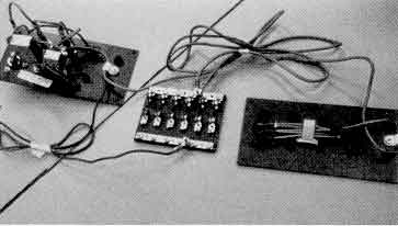
On all models there is a main wiring harness provided from the console switch panel aft to the battery. Inside the console is a 50 amp switch/circuit breaker which protects the main wiring harness. WHen off, all power to the switch panel is off. This prevents unauthorized use of electrical components.
Power is taken from the circuit breaker to the switch panel and, by a jumper wire, to a fused terminal block. This allows for easy rigging of any optional electrical accessory you may elect to add.
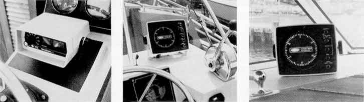
Optional instrument panels contain their own wiring harness which attaches to the engine ignition system to monitor voltage and RPM.
All models 18 to 25, including I/O and Sea Drive.
These hulls are equipped with fiberglass panels on both the port and starboard interior sides. The port panel covers the fuel fill and vent hoses. The starboard panel provides a convenient channel to run antenna lead wires from the forward section of the gunwale board to the console. On the floor under the panel you will notice a molded channel leading inboard. On Outrage models, the channel runs to the control cable opening under the console.
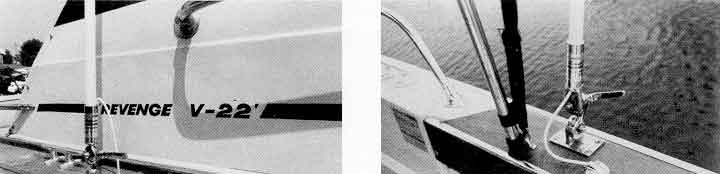
On Revenge models and Revenge Cuddy models antenna lead wires can be lead behind the fiberglass cabin side panel to the console radio shelf. On the Revenge 22 the bow rail presents a minor obstruction. If the antenna base is mounted inside the bow rail, it will be necessary to flatten the base on one edge and mount it as close as possible to the cabin. In this position, the antenna can be stored forward inside the bow rail. If the antenna base is outside the bow rail, the antenna can be stored aft along the gunwale.
On Outrage 18 and other Outrage models with smaller center consoles it is preferable to mount a radio under cover inside the console, convenient to the helm position.
Radios can be mounted on brackets suspended and bolted through from the console or on shelves built up from the console floor.
On 20, 22, and 25 Outrage models and I/O's equipped with the larger console a radio shelf is provided behind sliding Lexan® doors.
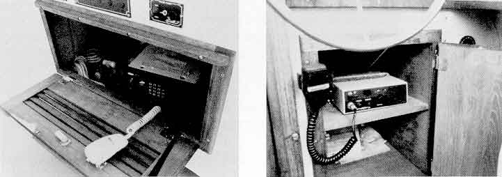
On Revenge 20 models, radios can be mounted on brackets above or below the steering console and remove for dry storage. On boats equipped with the optional bulkhead, radios can be mounted inside the storage box under the helm.
Revenge Cuddy and Revenge models, both 22 and 25, are equipped with a radio shelf and storage locker under the helm which is ideal for radio installation.
Depth finders will work at high speeds, serving the function of continuously recording depths and aiding in navigation. On 18, 20, and 22 models, transom mounted transducers must be used on Outboard, Sea Drive, and I/O models. On 25 models, there is a well or depression molded into the forward hull area for through-hull transducer installations. You will notice this area is covered by a separate fiberglass cover and teak access cover to a drain tube. Because the hull will require a fairing block, you will find transom mounted transducer installation easier and there will be less chance of damage with trailer operation. You may, therefore, prefer transom mounted transducers on the 25 models as well.
In selecting your fathometer, be sure the transducer is designed for transom mounting. Water flowing along the bottom of the boat must bass along the transducer face where no turbulence is created. Be sure the transducer is not in the path of any spray strakes on the bottom. This can best be done by carefully sighting over the transom with the boat at slow planning speed and marking the transom where there is a clear flow of water.
Using a straight edge along the bottom of the boat, bring the transducer face down so that it just touches the straight edge. Be sure that no portion of the leading edge of the transducer penetrates below the bottom of the hull. If there is a space between the transducer and the boat's transom, this space should be filled with either a compound or a facing piece. Some transducers are designed to hang below the boat bottom to pierce the flow of water. In some cases, it may be necessary to deflect the trailing edge of the transducer for contact with solid water. You will have to experiment. Remember, the secret to transducer success is ensuring a smooth flow of water on the transducer face.
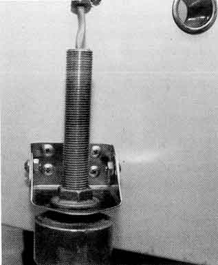
Most transducers will act as a small trim tab affecting boat trim. Transducers should be mounted on the port side to provide lift which will counteract the effects of the engine trim tab.
The area you select to mount the transducer on the transom may not contain wood inserts. The fiberglass skin is suitably strong for such fastenings as stainless steel sheet metal screws. The area behind the fiberglass is completely filled with closed cell foam so water entry is of no concern. However, bedding the transducer brackets in marine compound will strengthen the installation.
Choose the locatation of the depth finder carefully. Space on Outrage models equipped with smaller center consoles should be checked carefully as larger graph recorders may not fit the console top. There is ample room on the larger super console. On Revenge models, fathometers are best mounted on the port side under the windshield.
Depth finders should be temporarily mounted and turned on to determine their effect on compass deviation. If deviation occurs, locate the sounder as far away as practical. If deviation cannot be eliminated, record this influence at various headings with the fathometer on and off for future reference. Your Boston Whaler dealer can help you find the best location for your fathometer.
All compasses have variation and deviation. This is caused by the proximity of hardware and electrical components. Operation of certain electrical equipment such as windshield wiper motors, radios, and depth finders may cause significant compass deviation. Check compass readings prior to and during operation of the above mentioned electrical equipment and make note of the deviation for further references. CHECK YOUR COMPASS FOR DEVIATION.
DISCLAIMER: This information is believed to be accurate but there is no guarantee. We do our best!
The page has been accessed times.
Portions Copyright © 2005 by James W. Hebert. Unauthorized reproduction prohibited!
This is a verified HTML 4.0 document served to you from continuousWave
URI: http://continuouswave.com
Author: Adapted to HTML by James W. Hebert
This article first appeared February 5, 2005.