Sea Drive Conversion
Re-fitting a Boston Whaler OUTRAGE 18 Full Transom to Set Back Bracket
by Robert Schmidt
This article describes the process a friend and I went through when we replaced a Sea Drive unit on a 1985 Outrage 18. Brian (Bosler18) bought the boat in February 2005, after seeing it at a local yacht broker's yard. Several potential buyers had passed, and the dealer had dropped the price dramatically. Brian decided to make a low offer and if accepted, replace the Sea Drive with an Armstrong bracket or similar positive floatation engine bracket.
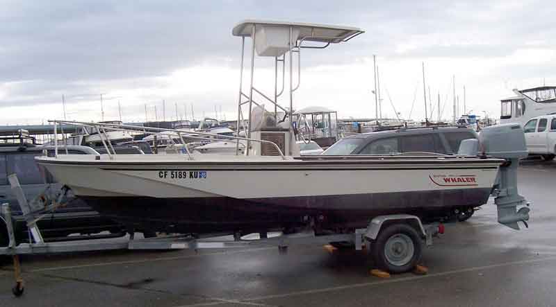 |
1985 Boston Whaler OUTRAGE 18 with Sea Drive
Brian's Outrage 18 at the time of purchase. We immediately removed the T-Top and restored the console and wood trim. We added a console rail (thanks Tom), rod holders (thanks Jeff), cooler cleats (thanks John), Wise swivel seats (thanks Joe), a 94-quart cooler, and gave her a through scrubbing. The boat now appears very much like it did the day it left the Boston Whaler factory (minus the terrible bottom paint application and a few odds and ends.) The gel coat was heavily oxidized, but otherwise in exceptional condition, however there are several marine-tex type repairs that will require attention at a later date.
Photo Credit: Robert Schmidt |
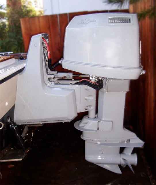 |
OMC Sea Drive
A close-up of the Sea Drive unit. Note the 30-inch set back. The bottom paint didn't even come close to reflecting the true waterline. It appears that the former owner simply drew a line from the transom, up the entire length of the hull. When at rest in the water, the true waterline ends around the middle of the console. This was due, in great part, to the weight of the Sea Drive unit, and the 30-inch engine set back. In addition, the original notched transom line is visible. This was probably a result of a mediocre fairing job.
Photo Credit: Robert Schmidt |
Now the depressing part. Fifteen minutes into the maiden voyage (while I was driving) the water pump failed, the overheat warning horn malfunctioned, and we destroyed the Sea Drives power head. The pre-purchase engine survey indicated low compression and other problems, however we were hoping to hobble through spring and summer. This was not to be.
After a healthy debate, and numerous discussions with members of the continuousWave forum, Brian decided to remove the Sea Drive. I credit Larry Goltz (LHG) for recommending we install a jack plate instead of a larger, heavier bracket. Larry believed that the Outrages low transom, combined with a moderate set back, would provide enough tilt to allow trailering. Larry also recommended using a hydraulic jack plate so that the motor could be elevated, then tilted, for mooring. After several more discussions, many debates, and not less than seven measurements, we decided to try it.
The first step was to de-rig the Sea Drive and drop it off the transom. The Sea Drive had six mounting bolts, a transom rigging plate, and some thru-hull assemblies that we had to protect from damage while sliding the unit off.
Removal was not as complicated as I thought. We started by disconnecting the control cables, battery cables, and wiring harnesses. These were run through the transom via a square hole in the top of the transom. The hole was trimmed outside the transom with a square bracket. The bracket had nipples inside the transom for the gas, oil, and hydraulic steering hoses. It also had two, 1-inch diameter holes that accommodated the control cables and wiring harnesses. These holes were sealed with rubber plugs, very similar to those on a normal outboards cowling. Once removed, the rubber grommets slid off the rigging and were out of the way. Then everything just slipped through the holes.
The hydraulic steering lines, gas line, and oil line are connected to the Sea Drive at the square bracket, then routed within the sea drive assembly itself. We simply disconnected these from inside the transom. We unplugged the tilt/trim wiring from the motor, which was located in the lower, circular hole. Again, access was easy from inside the transom.
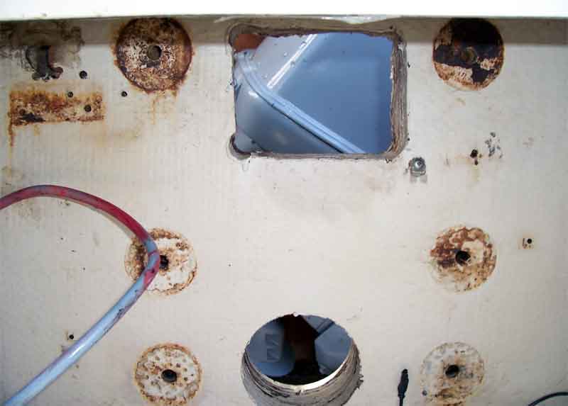 |
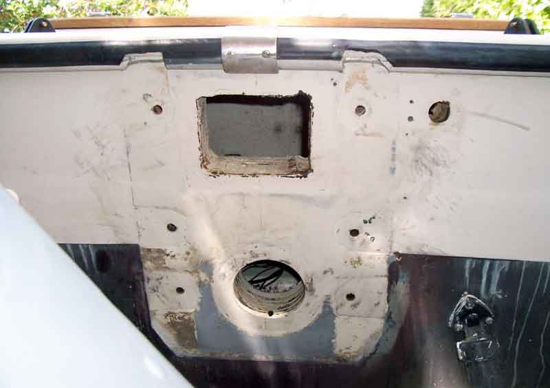
Transom
Here, we see the six mounting bolt locations, the square rigging cutout, and the circular hole that accommodates the trim/tilt motor. To the right was a tilt fluid reservoir, and to the left was the Sea Drive circuit breaker. Both were mounted to the inside of the transom with screws, which were removed, and the holes filled with sealant. In the upper left you can see a larger, 1-inch hole that eventually became the rigging tunnel for the new engine.
After all the rigging was clear, we supported the entire Sea Drive unit with a multitude of jacks and saw horses. Using the trailers tongue jack, we raised the front of the boat, simultaneously lowering the transom end, and thereby transferred the weight of the Sea Drive from the transom to the sawhorses/jacks. Once the mounting bolts were out, we slowly pulled the boat forward and worked the Sea Drive off. Oh man, they used lots of goo. Elbow grease, razor blades, adhesive remover, and Simple Green did the trick cleaning up the transom.
Photo Credit: Robert Schmidt |
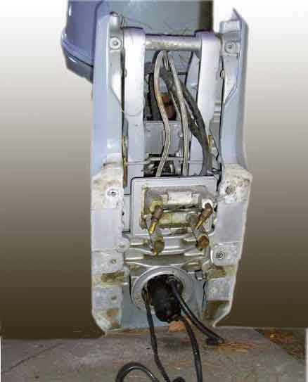 |
Sea Drive Mounting Bracket
Here, the Sea Drive has been removed. You can see the square rigging bracket, hydraulic steering couplers, and the gas/oil leads. Inside the gas/oil nipples are two 1-inch holes that accommodated the control cables and the wiring harnesses. Below, the trim/tilt pump and wiring, is visible.
With the Sea Drive removed and set aside, we cleaned the transom inside and out, then sent her off to the fiberglass shop for professional repair.
Photo Credit: Robert Schmidt |
 |
Sea Drive Mounting Bracket
Here, we see the six mounting bolt locations, the square rigging cutout, and the circular hole that accommodates the trim/tilt motor. To the right was a tilt fluid reservoir, and to the left was the Sea Drive circuit breaker. Both were mounted to the inside of the transom with screws, which were removed, and the holes filled with sealant. In the upper left you can see a larger, 1-inch hole that eventually became the rigging tunnel for the new engine.
After all the rigging was clear, we supported the entire Sea Drive unit with a multitude of jacks and saw horses. Using the trailers tongue jack, we raised the front of the boat, simultaneously lowering the transom end, and thereby transferred the weight of the Sea Drive from the transom to the sawhorses/jacks. Once the mounting bolts were out, we slowly pulled the boat forward and worked the Sea Drive off. Oh man, they used lots of goo. Elbow grease, razor blades, adhesive remover, and Simple Green did the trick cleaning up the transom.
Photo Credit: Robert Schmidt |
A view of the transom, from the outside. Note the cuts in the rub rail from the Sea Drive installation. If you look carefully, in the lowest circular cutout, you can see a small hole. This hole runs at a downward angle, through the transom, and into the splash well. It was apparently drilled as a drain for the tilt motor cutout. As far as I can tell, it was plugged with dirt, and had never been properly sealed. Yikes!
Unfortunately, the fiberglass shop took over a month to complete out little project, and at double the original estimate. Thats another story. Anyway, I regret that I was not able to get any photos of the transom restoration in progress. I do know that the larger holes were plugged with 3 layers of -inch plywood with epoxy laminates in between each layer, and -inch fiberglass matt and resin on the inside and outside. The mounting holes were repaired with wood plugs and epoxy. The outside was finished with a few layers of Spectrum color-matched gel coat, sanded, and polished to a shine. The inside, since it is not visible, was simply finished with a brushed layer of gel coat.
While we were waiting for the fiberglass shop, and before to choosing the jack plate, I spoke with Chuck Bennett at Boston Whaler, and he gave the thumbs up for mounting a jack plate through the transom insert, if needed. Apparently there was quite a bit of reinforcement added to accommodate the Sea Drive, and he did not think this would present any sort of problem. The transom was at least 3-inches thick! I also confirmed with Chuck that our Outrage-18 had a 14-degree transom angle.
We began looking seriously at a Slidemaster 12-inch manual jack plate. I called Slidemaster, and was surprised they asked so many questions about the boat. Come on people, I thought, just tell me about your jack plate and quit asking me about make, model and transom angles. Well, as it turns out, Im glad they did. More on this later.
Back to the point. Slidemaster offered the longest setback for the lowest price. I also investigated Armstrong and Stainless Marine mini-brackets, but these were much more expensive, back ordered, and did not offer the adjustability of a jack plate. After quite a bit of research, the plan was formulated; mount a Slidemaster manual jack plate, find the ideal height adjustment using the jack plate's manual adjustments, then decide whether to keep the jack plate as is, add a hydraulic unit, or replace the whole deal with an Armstrong bracket. For the initial set up, and since this was sort of an experiment, we selected a 12-inch Slidemaster, the least expensive option that offered the most flexibility.
Now, where to mount the jack plate. I researched the standard mounting pattern for this engine using the continuousWave FAQ section, on a typical notched transom, and came up with the following measurements:
"The top pair of holes are spaced 12 and 7/8-inch on center; each hole is 6 and 7/16-inch from the engine bracket centerline. The bottom pair of holes are spaced 9 and 7/8-inch on center; each hole is 4 and 15/16-inch from the engine bracket centerline. The spacing between the top and bottom pair of holes is 8-inches on center. The centerline of the top holes is 2-inches below the top of the engine bracket. The holes in the transom should be 1 and 7/8-inch below the top of the transom. In no case should they be closer than 1 and 3/4-inch to the top of the transom. When locating holes on the transom, do not assume the top of the transom is a straight or true edge. Determine the transom vertical centerline by measuring equal distances from the hull's chines. Align the engine mounting holes to the true vertical centerline of the transom, not to the top edge of the transom."
Again, with the guidance of Larry Goltz (LHG), we determined that the jack plate should be mounted in the standard notched transom engine mounting location. This is where the math came in, and a major mistake was avoided. I had a friend run the calculations, and with the 14-degree transom angle, combined with the 12-inch set back, I should mount a 90-degree jack plate 2.9 inches higher than the standard transom mount. Jim Hebert also confirmed these calculations. In addition, water rises approximately 1-inch for every 12-inches of set back when the boat is on a plane. This means that a 90-degree jack plate would be mounted 3.9 inches higher on our transom than a typical notched transom, and would put the top mounting bolts right through the transom insert. Not a problem, according to Chuck Bennett.
Here's the thing, though. Slidemaster, in their infinite wisdom, sent me a jack plate with a built-in 14-degree lift angle, and an additional 1-inch rise on the engine mount plate. The jack plate was already designed to be mounted in standard mounting holes for a notched transom, and its design incorporated the additional height needed due to transom angle and set back. The friendly people at Slidemaster offered to allow us to return the manual jack plate for credit toward a 12-inch hydraulic unit if we were unsuccessful in our endeavor. The Slidemaster jack plate was fabricated and shipped within a week, and came with all the hardware needed to mount the engine to the jack plate.
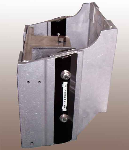 |
Set-Back Bracket and Jack Plate
The jack plate is not a 90-degree square, but more of a parallelogram, with an additional one-inch rise at the engine mount plate.
Photo Credit: Robert Schmidt |
The boat returned from the fiberglass shop, and we set about mounting the jack plate. The first step was to determine exactly where the standard notched transom mounting position was. This sounds easy, but remember, we did not have any reference points because this was now a blank transom.
Ugh, more math. We knew from the continuousWave FAQ section that the centerline of the top holes is 2-inches below the top of the engine bracket, and that the top of the engine bracket to the anti-cavitation plate was 25-inches. Therefore, in order to mount an engine with the anti-cavitation plate level with the lowest point on the transom, the centerline of the top holes would be 23-inches above the lowest point on the transom. In addition, we knew from Chuck Bennett that our Outrage started its life as a normal, notched transom Outrage-18, and then Whaler epoxied 3 layers of 1/2-inch plywood into the notch, followed by another full inch layer of resin/matting inside the transom, to create a full transom. The outside of the transom notch insert was simply faired to match the rest of the transom. The full transom insert was approximately 8-inches wide. Therefore, we deduced that the centerline of the top holes would be 10-inches from the top of the full transom. Sure enough, when we set about measuring, the total length of the full transom was 33 inches; the centerline of the top holes was 23-inches above the lowest point on the transom, and 10-inches from the top of the full transom.
With that problem solved, we ran into another measuring problem. We were having difficulty determining the transom vertical centerline. We were measuring equal distances from side of the hull and the chines, however we were dealing with rounded edges, and the slightest variance in tape measure positioning was causing misalignment of the true vertical centerline of the transom. Our solution was to use a carpenters square to measure several points on the transom that were marked 2-inches in from the transom/hull intersection, at equal heights from the bottom of the transom. With these points defined, it was easy to mark the transom vertical centerline. We used the same reference points to snap two horizontal chalk lines. The first was the notched-transom line, and the second, 1 and 7/8-inch below, was the centerline of the top holes.
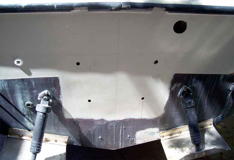 |
Repaired Transom
The repaired transom, with the new rigging tunnel and mounting holes drilled. The transom vertical centerline, notched transom line, and top-hole centerline are also visible. The bilge pump thru-hull made it difficult to measure a straight line. We solved this problem by using a chalk line. That is Git-Rot running from the lower mounting hole, not water!
Photo Credit: Robert Schmidt |
We measured the drill points at 6 and 7/16-inch from the engine bracket centerline, and then held the jack plate up against the transom to ensure a perfect fit. Once we were sure the top holes were correctly measured and marked, we used a inch drill bit as a pilot hole. In order to drill the 1/2-inch mounting holes at a 90-degree angle to the transom, we used a template made from a 2x4, with a 1/2-inch drill-press drilled center hole. The 2x4 guide was then pressed flat against the hull, the drill bit inserted through the template and into the pilot hole, for a perfect 90-degree hole. Once the top holes were drilled, we dry mounted the jack plate using 1/2 x 5-inch stainless steel bolts, and marked the bottom holes. Surprisingly, there was a fair amount of play without the bottom holes mounted, and we had to center the bracket by hand tightening the upper mounting bolts, and aligning the centerline of the jack plate with the transom vertical centerline in order to achieve perfect symmetry.
With the bottom holes marked, we removed the jack plate, and checked our measurements again. Indeed, the bottom pair of holes were spaced 9 and 7/8-inch on center; each hole was 4 and 15/16-inch from the engine bracket centerline. The spacing between the top and bottom pair of holes was 8-inches on center. More drilling and another dry mount later, we were ready to begin final installation of the jack plate.
In the meantime, we drilled a 2-inch rigging hole on the starboard side of the transom, close to the top of the transom insert. There was a pre-existing 1-inch hole in this the location, purpose unknown, so we decided to just enlarge it and run the rigging through. We feathered the interior and exterior gel coat of the mounting and rigging holes with a round file and sandpaper, and applied some Git-Rot epoxy to the exposed plywood inside the holes to seal them. The next day, we applied polysulfide sealant to the jack plate, hull, mounting bolts, holes, and anywhere else we could think of, and bolted the jack plate to the hull using four 5-inch Stainless Steel mounting bolts, eight 2.5-inch fender washers, four 1/2-inch fender washers, and four 1/2-inch Nylock nuts. We cleaned up the excess sealant, and gave the remaining sealant time to cure.
Larry recommended the following mounting procedure for the jack plate.
"This is Mercury's recommended engine mounting process, and allows for proper sealing and resistance to engine stress applied to the transom. First put the bolts though the top holes in the transom, putting a ring of caulking around the bolt SHANK and under the washer. Push though hull, and then put another ring of caulking around the bolt on the outside. Then, put the bottom bolts through the jack plate, and put a ring of caulking around the bolt shank and about 1" on to the shank. Then, holding the bottom bolts in place so they go all the way through to the inside, put the bracket in place on the transom, making sure the top bolts do not get pushed back in at all. All four outside holes will be nicely filled with caulking, but you will not get any caulking on the threads or nuts. Then finally, put a ring of caulking round the bottom bolts on the inside, and press on the washers and nuts. If you do this correctly, you will have a totally watertight jack plate installation. Let cure for 24 hours."
 |
Bracket Mounted to Hull
The camera angle may cause the jack plate to appear skewed. Believe me, it is not.
Photo Credit: Robert Schmidt |
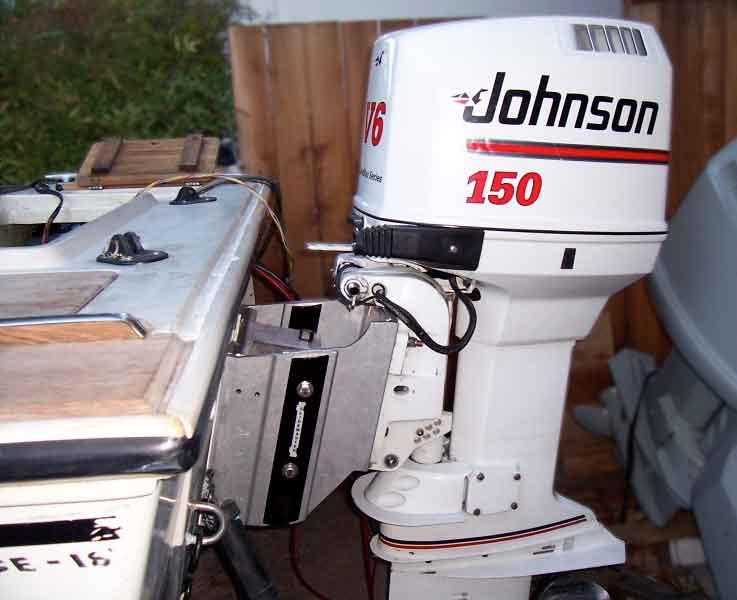 |
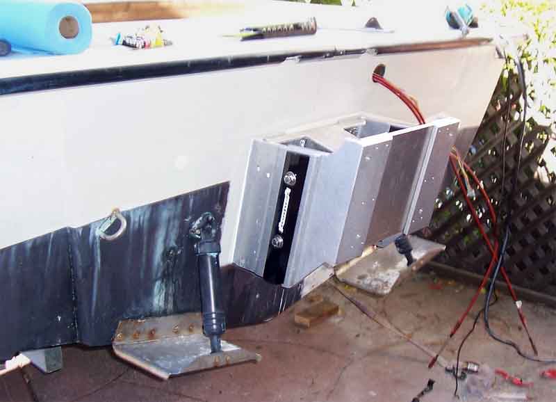
Bracket Mounted to Hull
After the jack plate was installed, we located, bought, and mounted a 1991 Johnson 150 Silver Star Series engine to the jack plate.
Photo Credit: Robert Schmidt |
With the engine mounted, we could see that there was sufficient tilt for trailering. I began to suspect that we might have enough tilt to allow the foot of the engine to clear the waterline. In the background, you can see the old Sea Drive. The weight difference between the new engine and the Sea Drive is staggering; I estimate that the new set up is at least 250 Lbs. lighter.
Rigging the engine was not a problem, but it did take several tries. The existing control cables were sufficiently long to allow re-use. The original Seastar I helm and hydraulic lines were also used, although the original hydraulic lines were too short for a center mount cylinder. They fit perfectly on the side mount cylinder located on the starboard side, next to the rigging tunnel. The ignition wiring harness, control box, key switch, (now functional) warning horn, and tachometer were also compatible. We installed a trim gauge and trim wiring harness, as the one from the Sea Drive was a select trim and apparently not compatible. Luckily, we scrounged these parts from the prior owner of the Johnson. (thanks Brian)
The main problem with rigging the outboard to the full transom is the proximity of the engine to the transom. I think this is a unique result of the conversion to the jack plate. With the full transom, the cables are below the engine cable entry, and tilting/turning the engine with a straight run creates a sharp bend in the cables. Our solution to minimize this effect and allow full turning radius was to place a loop outside the transom. On our Outrage, the rigging tunnel was drilled as high as possible, yet so close to the engine that awkward angles are created when turning/tilting/trimming. With no slack to allow turning, we decided to recreate the loop outside the transom. So far it has worked fine, however I think that the cables are so old that they are still binding a bit. (They are also Teleflex red jacket cables, and the bulky OMC engine adapters don't work so well with the Silver Star 150's control cable grommet.) Currently, the only "binding" is between the S-shaped, split loom rigging tube and the transom rub rail when the motor is tilted all the way down, as seen in the picture below. When trimmed up and/or tilted, the wiring harness drops below the rub rail, and there is no problem. The hydraulic lines are connected to a static side mount cylinder, and therefore do not move with the engine. These are not a problem. Following Larry's advice, we will eventually re-rig the control cables without the loop, and move the hydraulic cylinder to the port side.
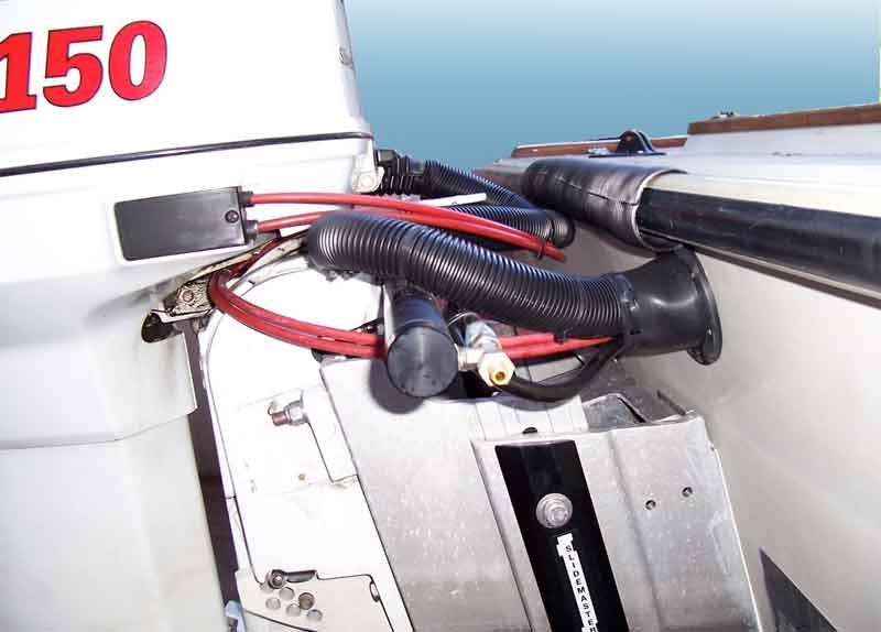 |
Rigging Details
The control cables, hydraulic lines, wiring harnesses, and gas/oil lines are installed. We completed the installation with a T-H Marine rigging flange and some rigging tubing, for a nice, finished look. At the trial run, we were able to achieve enough trim to allow trailering, and mooring. The tip of the gear case was still in the water, but at least the propeller and water intakes were clear. We also determined that the engine could be raised another few inches using the jack plate's manual adjustments. We were only able to achieve cavitation with maximum trim, and even then she was only running 5,000-RPM at WOT.
Photo Credit: Robert Schmidt |
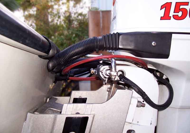 |
Rigging Details
Port side view of rigging.
Photo Credit: Robert Schmidt |
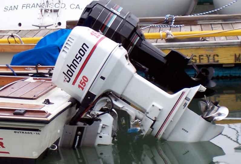 |
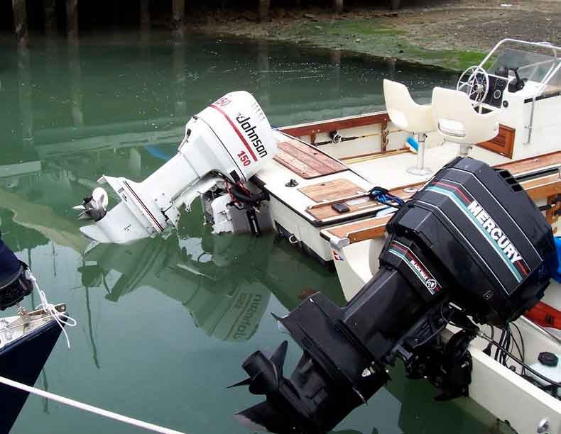
In the Water
A view of the transom after a trial run. We are rafted to Matt Frymiers 1982 Outrage 18.
Photo Credit: Robert Schmidt |
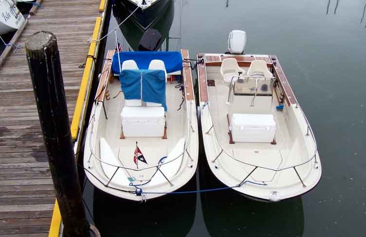 |
In the Water
A view of the completed conversion (right) and a standard notched transom Outrage 18 (left). The other Outrage 18 has a 1991 Mercury Black Max.
Photo Credit: Robert Schmidt |
 |
Static Trim
Our converted Outrage sits a few inches lower in the stern than the other Outrage.
Photo Credit: Robert Schmidt |
Following the trial run, we raised the engine an additional 1.5-inches, which improved performance and allowed the engine to tilt completely of the water when moored. Using a hand held GPS, we recorded the following information:
Test Results
Background information:
- 1985 Outrage-18.
- Bottom paint.
- Reinforced full transom, and stern lazerettes.
- Group-27 lead-acid battery located in the starboard stern lazarette.
- 12-inch Slidemaster manual jack plate, 1.5 inches of additional vertical adjustment.
- Cavitation plate approximately 2.5 inches above the lowest transom point.
- 1991 Johnson 150 HP Silver Star engine.
- Four-blade stainless steel propeller.
- 20 gallons of fuel. Racor fuel/water separator.
- Seastar side mount cylinder.
- Standard USCG required safety equipment: 4 life jackets.
- 18 lb. Danforth Anchor, 6 feet of galvanized chain in the bow locker.
- Bennett trim tabs, fully retracted.
- 2 crew at 460 LBS.
Performance Notes
- The maximum speed at wide open throttle is 46-MPH at 5,100-RPM.
- The boat rides very flat in the water while at plane, even without use of trim tabs.
- An engine speed of 3,000-RPM is required to achieve a plane, however the boat will hold a plane at 2,600-RPM at 23-MPH.
- An engine speed of 3,000-RPM gives a good cruising boat speed of 27.5-MPH.
- WOT is achieved with engine trim adjustment just below cavitation point.
- The boat sits about 2- to 3-inches lower in the stern than a standard Outrage 18.
- Further performance results pending.
After raising the engine an additional 1.5 inches and extending the trim tabs even with the keel, we were able to achieve 5,500-RPM engine speed and a boat speed of aproximately 49-MPH (measured via GPS) on flat water. The best part was that the additional engine height allowed us to achieve our ultimate goal: full engine tilt.
Things I Learned
Here is a short list of some things I learned during this project:
- Always check your warning horn.
- Sea Drive owners may want to clean and seal that small drain hole. The Sea Drive is very heavy, and takes 4 big guys to maneuver once it is off the transom. No one wants to buy a used Sea Drive.
- Always get a written estimate for fiberglass repair, even if it is an acquaintance doing the work.
- A center-mount Seastar hydraulic cylinder has too many moving parts for this application. The space between the engine and transom is barely wide enough for the rigging. A side mount cylinder is a great match, and may be mounted on the starboard side using the original hydraulic lines, but it is preferable to mount it on the port to compensate for engine pull.
- Larry knows more about Whalers than I ever will.
- Twenty-foot hydraulic lines would allow the Seastar cylinder to be mounted on the port side. The T-H Marine rigging flange is 3-inches in diameter, and the cutout need only be 2-inches in diameter.
- Git-Rot is great stuff for sealing mounting holes. It is a slow-cure viscous epoxy that absorbs into untreated plywood quickly and cleanly.
- Use a carpenter's square to measure transom points, and a chalk snap line to achieve straight lines.
- Feather the gel coat before dry mounting a heavy jack plate. We chipped the holes up a bit.
Final costs (not including hull and engine):
- Slidemaster 12-inch jack plate: $235.00
- Seastar Side mount cylinder: $289.00
- Fiberglass work: $900.00
- Mounting/Rigging hardware: $80.00.
- 6-feet oil tubing for VRO: $12.00
- 5-feet split loom 1.5-inch cable wrap: $11.50
- Git Rot: $23.50
- Polysulfide caulk: $9.00
- T-H Marine flange: $9.00
- 2 quarts hydraulic steering fluid: $23.00
Items reused:
- Seastar I Hydraulic helm and tubing.
- Control box and cables
- Ignition wiring harness
- Key switch
- Warning horn
- Tachometer
- Volt meter
- VRO tank
- Water pressure gauge, tubing.
- Trim gauge and wiring harness
- Racor fuel filter
- Fuel lines
Brian and I extend our heartfelt thanks to Larry Goltz, Jim Hebert, and the entire continuousWave community. Without your guidance, patience, suggestions, and help this project would not have been possible. --Rob Schmidt
Further Discussion
Questions and comments on this article can be posted to a discussion reserved for that purpose.
DISCLAIMER: This information is believed to be accurate but there is no
guarantee. We do our best!
Copyright © 2006 by Robert Schmidt and James W. Hebert. Unauthorized reproduction prohibited!
This is a verified HTML 4.0 document served to you from continuousWave
URI: http://continuouswave.com
Last modified:
Author: Robert Schmidt. Converted to HTML by James W. Hebert
This article first appeared July 9, 2006.