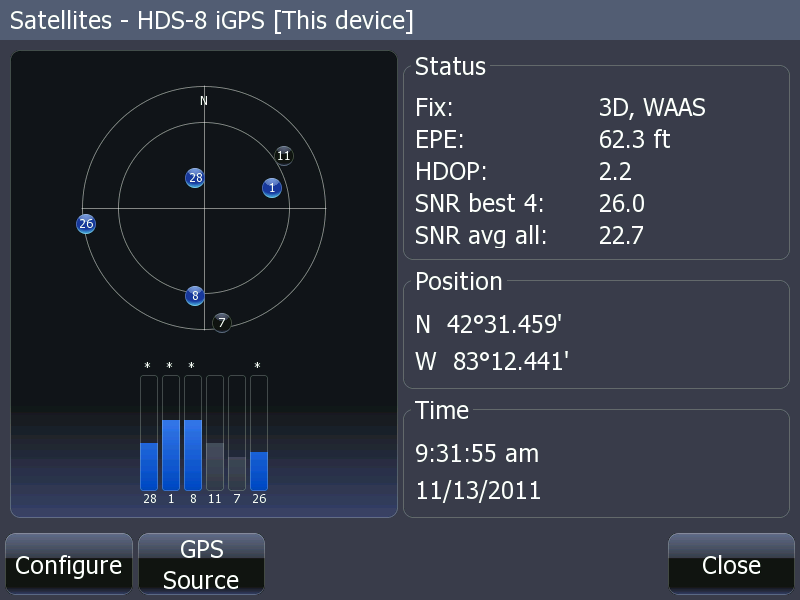
The GPS data we want to send to the radio.
A consistent method for interfacing of NMEA-0183 serial data ports is presented.
Update: March 2014. Three years ago I looked at the problem of NMEA-0183 interfacing with a goal of developing a universal solution. I described a solution I developed using a five-pole connector wiring. I have since developed an improved version, which I will now describe. The only difference in this version from the original is my connector pin layout for use with the five-pin headers and backplane that I used for my implementation of the method. The location of the signals on the five pins has changed slightly in order to greatly simplify the wiring of the backplane.
This method allows simple interconnection of NMEA-0183 signals from either a single-ended or differential TALKER to either a single-ended or differential LISTENER. I have also written a separate article, Guide to NMA-0183 Interconnections, that describes the rules used to make these interfaces. The guide also explains how to interpret the many non-standard names or designators that manufacturers give to their signals. I recommend reading the guide, too, in order to better understand the interconnection method used here.
In NMEA-0183 the standard calls for the serial data interfaces to be differential signals, but many manufacturers ignore that and use single-ended interfaces. It is actually quite common among NMEA-0183 devices that a single device could have both types of ports. For each NMEA-0183 port we have a TALKER and a LISTENER, and either or both can be differential or single-ended. This mean there are four possible configurations for an NMEA-0183 port:
When interfacing two NMEA-0183 ports, we have to account for all the possible combinations of these four arrangements. There are ten possible combinations:
The goal is to find a consistent wiring arrangement that will allow the interconnection of these four different interface configurations in all ten combinations so that their interconnection at the interface is always the same. If a five-pole or five pin interconnection is used, it is possible to create a consistent method of wiring that will work in all situations. I will describe the method below.
First, I will describe the four different wiring configurations for the transmit and receive signals to be wired to the five poles. I call the poles A-B-C-D-E. The table below shows how to connect the NMEA-0183 signals to the five poles in the four possible arrangements of transmit and receive circuits that exist in the various implementations found in devices in the field:
| TALKER and LISTENER Differential | |
|---|---|
| POLE | SIGNAL |
| A | TALKER A |
| B | TALKER B |
| C | GND or chassis or shield |
| D | LISTENER B |
| E | LISTENER A |
| TALKER Single-end; LISTENER Differential | |
|---|---|
| POLE | SIGNAL |
| A | TALKER A |
| B | GND or jumper to C |
| C | GND |
| D | LISTENER B |
| E | LISTENER A |
| TALKER Differential; LISTENER Single-ended | |
|---|---|
| POLE | SIGNAL |
| A | TALKER A |
| B | TALKER B |
| C | GND or chassis or shield |
| D | No connection |
| E | LISTENER A |
| TALKER and LISTENER Both Single-ended | |
|---|---|
| POLE | SIGNAL |
| A | TALKER A |
| B | GND or jumper to C |
| C | GND or chassis or shield |
| D | No connection |
| E | LISTENER A |
Note that for single-ended TALKER arrangements you must have a GND at "B", and it can be either via the cable or via a jumper to "C".
If the NMEA-0183 signals are always wired following the convention noted above, then they can always be interconnected using a consistent wiring arrangement. That universal arrangement is as follows, again notated using the five poles as A-B-C-D-E. The first device is denoted with suffix "1" and the second device with suffix "2". We interconnect the device with a consistent method, as follows:
| Interconnect Wiring | |
|---|---|
| FIRST DEVICE | SECOND DEVICE |
| A1 | E2 |
| B1 | D2 |
| C1 | C2 |
| D1 | B2 |
| E1 | A2 |
The C1 and C2 terminals are also wired to the power negative or ground. The interconnection wiring can be accomplished in several ways. I implemented by building a small circuit board or backplane with four sets of headers. The headers are interconnected in pairs. However many arrangements are possible.
The problem of interconnection is now very simple. One must identify which type of interface is being used, i.e., is the device interface differential, single-ended, or a combination. Next, one identifies the wire colors which are used for each signal, and then those signals are wired to a five-pole interface according to the scheme shown above. Using this approach, it should be possible to interconnect any two NMEA-0183 devices with the method described above. This is truly a universal solution.
The wiring arrangement is now solved by a universal method of interconnection. I am not proposing that a specific connector be used. In fact, no connector is needed. One could wire devices to terminal strips or binding posts and then interconnect them as I have described. Later I will show a connector arrangement using very inexpensive devices which can be interconnected using a pre-wired backplane.
For devices that have multiple NMEA-0183 ports, each port is handled independently. A device with, say, two NMEA-0183 ports would have two five-pole interconnects wired to it, one for each port.
Many manufacturers label the NMEA-0183 port signals with non-standard names. The signal that NMEA calls TALKER A is often called "Tx+" or "Out+" or something similar. The signal that NMEA calls TALKER B is often called "Tx-" or "Out-" or something similar.
The signal that NMEA calls LISTENER A is often called "Rx+" or "In+" or something similar. The signal that NMEA calls LISTENER B is often called "Rx-" or "In-" or something similar.
The use of the plus and minus signs on the signals should not be confused as being the polarity of a DC circuit. In a differential circuit the minus sign is often used to indicate the inverted signal, and the plus sign to indicate the non-inverted signal.
Let's look at an example using the Lowrance HDS-8 configured as a differential device. Lowrance calls this mode "RS-422." In this mode the device has differential TALKER and differential LISTENER ports. The standard wiring to the five-pole connector will be:
| Lowrance HDS-8 RS-422 | ||
|---|---|---|
| POLE | SIGNAL | WIRE COLOR |
| A | TALKER A | YELLOW |
| B | TALKER B | BLUE |
| C | GND | Shield |
| D | LISTENER B | GREEN |
| E | LISTENER A | ORANGE |
The Lowrance HDS-8 can also be configured to have two single-ended serial communication ports. Lowrance calls this mode "RS-2323." This configuration has has single-ended TALKER and single-ended LISTENER ports. The standard wiring to the five-pole connector will be as shown below, with a separate table for each of the two ports:
| Lowrance HDS-8 RS-232 | ||
|---|---|---|
| POLE | SIGNAL | WIRE COLOR |
| A | TALKER A | YELLOW |
| B | TALKER B | Jumper to C |
| C | GND | Shield; jumper to B |
| D | LISTENER B | No connection |
| E | LISTENER A | ORANGE |
| Lowrance HDS-8 RS-232 | ||
|---|---|---|
| POLE | SIGNAL | WIRE COLOR |
| A | TALKER A | BLUE |
| B | TALKER B | Jumper to C |
| C | GND | Shield; jumper to B |
| D | LISTENER B | No connection |
| E | LISTENER A | GREEN |
Similarly, the Standard-Horizon GX1500S is also a differential device on both ports, and would be wired as follows:
| Standard-Horizon GX1500s | ||
|---|---|---|
| POLE | SIGNAL | WIRE COLOR |
| A | TALKER A | GRAY |
| B | TALKER B | BROWN |
| C | GND | Shield |
| D | LISTENER B | GREEN |
| E | LISTENER A | BLUE |
Some interpretation of the manufacturer's nomenclature is needed. S-H refers to the signals as "NMEA OUT" for TALKER and "NMEA IN" for LISTENER. Most users should not have a problem making this association.
We see that the interconnection of these two devices using the universal wiring configuration works perfectly. To test the applicability of the method, I will try a few other random devices to see if they can be interfaced this way.
A popular VHF Marine Band radio is the ICOM M422. Its NMEA interface consists of just two wires: a red conductor is the "NMEA IN LEAD" which is interpreted as the LISTENER A signal. A white conductor is the "NMEA OUT LEAD" which is interpreted as the TALKER A signal. Here again we see the inconsistency in labeling of the signals and total inconsistency in the wire insulation color coding. The device is clearly a single-ended device, on both the transmit and receiver signals. The wiring of the M422 to the five-pole interface is thus:
| ICOM M422 | ||
|---|---|---|
| POLE | SIGNAL | WIRE COLOR |
| A | TALKER A | WHITE |
| B | TALKER B | GND via jumper to C |
| C | GND | Not provided; jumper to B |
| D | LISTENER B | No connection |
| E | LISTENER A | RED |
The ICOM M422 does not provide any shield or chassis or ground lead. We can use the power negative lead (almost universally the black wire of a red-black pair) to be the source for a conductor, or we can omit the conductor entirely and depend on the power negative circuit between the M422 and other devices to complete the circuit. That approach will usually work if the two devices are powered by a common power source--typical on a small boat--and the common power circuit is not too distant. Since the devices are typically connected to the same secondary power distribution panel, the common circuit path will usually be only a few feet in length and should be suitable.
The RAYMARINE A70 is part of the A-Series of devices from RAYMARINE. It offers two NMEA-0183 ports. Each port is a differential port for both TALKER and LISTENER. The nomenclature of the RAYMARINE refers to the signals as IN and OUT signals and denotes them as either "+ve" or "-ve". This is interpreted as IN means LISTENER, OUT means TALKER, "+ve" means "A" and "-ve" means "B". The five-pole wiring will then be:
| RAYMARINE A-Series Primary Port | ||
|---|---|---|
| POLE | SIGNAL | WIRE COLOR |
| A | TALKER A | YELLOW |
| B | TALKER B | BROWN |
| C | GND | (not provided) |
| D | LISTNER B | GREEN |
| E | LISTENER A | WHITE |
| RAYMARINE A-Series Secondary Port | ||
| POLE | SIGNAL | WIRE COLOR |
| A | TALKER A | ORANGE-YELLOW |
| B | TALKER B | ORANGE-BROWN |
| C | GND | (not provided) |
| D | LISTENER B | ORANGE-GREEN |
| E | LISTENER A | ORANGE-WHITE |
With differential signals, the ground or shield or chassis conductor is not required for the electrical connection, and can be omitted. The common power connection will be relied upon when interfacing to unbalanced devices.
GARMIN is a popular manufacturer of marine electronics. We look at their popular GPSMAP 700-series devices and the NMEA-0183 interfaces used. The nomenclature used is very straightforward: Garmin refers to the signals as "Tx (out)" and "Rx (in)". The ports are single-ended for both transmit and receive and there are two ports. The wiring to the five-pole connector is thus:
| GARMIN 700 Series Primary Port | ||
|---|---|---|
| POLE | SIGNAL | WIRE COLOR |
| A | TALKER A | BLUE |
| B | TALKER B | jumper to C |
| C | GND | BLACK (of power cable) |
| D | LISTENER B | no connection |
| E | LISTENER A | BROWN |
| GARMIN 700 Series Secondary Port | ||
| POLE | SIGNAL | WIRE COLOR |
| A | TALKER A | GRAY |
| B | TALKER B | jumper to C |
| C | GND | BLACK (of power cable) |
| D | LISTENER B | no connection |
| E | LISTENER A | VIOLET |
Again there is not a separate NMEA ground conductor, and the power negative lead must be used. A dedicated conductor can be wired to the power negative and run to the five-pole connector, or the power circuit common can be relied upon without running a new conductor.
The SIMRAD NSS models have NMEA-0183 ports that are (RS-422) differential TALKER and differential LISTENER, but they can be set to single-ended (RS-232) The wiring for the RS-422 configuration, as shown in the current instruction manual is:
| SIMRAD NSE Series from Installation Manual | ||
|---|---|---|
| POLE | SIGNAL | WIRE COLOR |
| A | TALKER A | YELLOW |
| B | TALKER B | BLUE |
| C | GND | (not provided) |
| D | LISTENER B | ORANGE |
| E | LISTENER A | GREEN |
Apparently there was some change in production, and some units were wired with a color code of wires in the data cable. SIMRAD sent on an errata sheet to owners of these models. The information below comes from an errata sheet sent with a recently installed unit. As can be seen, the polarity conventions are inverted with respect to the information from the manual.
| SIMRAD NSS Series from Errata Sheet | ||
|---|---|---|
| POLE | SIGNAL | WIRE COLOR |
| A | TALKER A | BLUE |
| B | TALKER B | YELLOW |
| C | GND | (not provided) |
| D | LISTENER B | GREEN |
| E | LISTENER A | ORANGE |
To test my universal NMEA-0183 interconnection method, I wired up two NMEA-0183 devices on my bench with five-pole connectors. For the cable-end connectors coming from the devices I used a very inexpensive MOLEX 0.100-inch terminal housing connector. For the mating connector I used a mating MOLEX 0.100-inch pin header. I selected the forms with pins and locking tabs. The cable end connectors are wired by using small crimp terminals and crimping the terminals onto the wires of the cable. You then slide the terminals into the back of the connector housing. There is a small latch spring on the terminal that captivates the terminal in the housing, but you can easily release the terminal and withdraw it, if you need to at a later time. Crimping the terminals requires a particular crimp tool. I happen to have a MOLEX crimp tool which does a very good job on these terminals. The tool rolls the sides of the crimp over and down onto the wire. There is also a second crimp to grab onto the wire insulation to give more strength to the terminal-to-wire joint.
These terminals are rather small, and you have to have some skill in handling them. They're not for the ham-fisted assembler. The crimp has to be the right size, too, or the terminal will not slide into the housing correctly. However, if you can overcome these difficulties, this connector makes a very small, very inexpensive five pole connector for about a $1 cost.
I mounted the pin headers on a small circuit board I found at RADIO SHACK. Normally I eschew purchase of anything at RADIO SHACK, but they happen to have a very handy pre-drilled experimenters circuit board that provides an appropriate pin layout for mounting four 5-pin headers and easily interconnecting them. I soldered four headers on the experimenter's circuit board, and then used some short jumpers to interconnect them with my universal NMEA-0183 interconnection arrangement. Again, that arrangement is:
| Backplane Wiring | |
|---|---|
| FIRST DEVICE | SECOND DEVICE |
| A1 | E2 |
| B1 | D2 |
| C1 | C2 |
| D1 | B2 |
| E1 | A2 |
The RADIO SHACK circuit board is not pre-tinned, but the copper is quite clean (which is not always the case with these products) and it took solder easily. The lands for the solder pads are closely spaced, and care must be taken not to make a solder bridge between adjacent lands. Use a micro-chisel tip and a soldering pencil of appropriate wattage.
The two devices I had on the bench for testing were my HDS-8 and my GX1500S. The GX1500S can only be set-up one way: differential receiver and differential transmitter. I crimped the four conductors and inserted them in the terminal housing. I used the layout I previously determined (see above). The HDS-8 can be configured as either a single pair differential receiver-transmitter or as a dual pair of single-ended receiver-transmitters. For my first test configuration I used the single pair differential receiver-transmitter configuration. I crimped on the terminals and inserted the wires into the housing. Again, I used the layout I previously determined (see above).
With the two devices wired to their universal five pole connectors, the interconnection should now consist of just pushing the terminals onto the pre-wired backplane interconnection device. Now to see if it works!
I powered-on the HDS-8 and let it acquire a position fix. Then I turned on the GX1500S. The radio immediately showed it was receiving data from the GPS receiver via its NMEA-0183 interface. The universal wiring arrangement worked perfectly. I shut everything off and moved to the next test.
The GPS data we want to send to the radio.
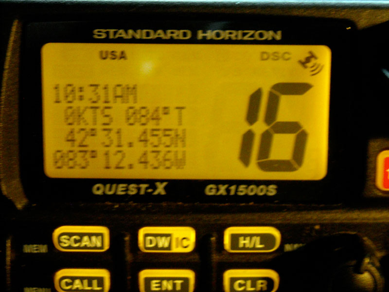
The radio display that confirms the interface is working.
Next, I reconfigured the HDS-8 to switch to single-ended receiver-transmitter ports. Then I re-wired the conductors from the HDS-8 to the terminal housings. This is where the removable crimp terminals came in handy. Using a very small screwdriver, I was able to easily release the terminals from the housing and reposition them. Since the HDS-8 now has two ports, I needed two housings. I wired the single-ended ports as I had previously determined (see above), but I had to add a jumper between poles B and C on each terminal. Without this jumper, the differential receiver of the GX1500S would not recognize any data.
With the terminal housing reconfigured, the universal interface interconnection worked again. Since I had two outputs from the HDS-8 I could move my GX1500 connection to either one. They both worked fine.
Here are some details of the connectors I used:
As you can see the component costs for the connectors and backplane wiring device are very low. To assemble each port required only five terminals and a housing at a cost of $0.65. To make a backplane interconnect with four ports costs about $3.75 in components and a bit of wire and solder.
Some images of the interface and its components:
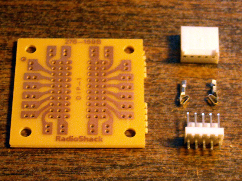
The connector components on the right. From top to bottom: housing, terminals, header. On the left the pre-fab circuit board.
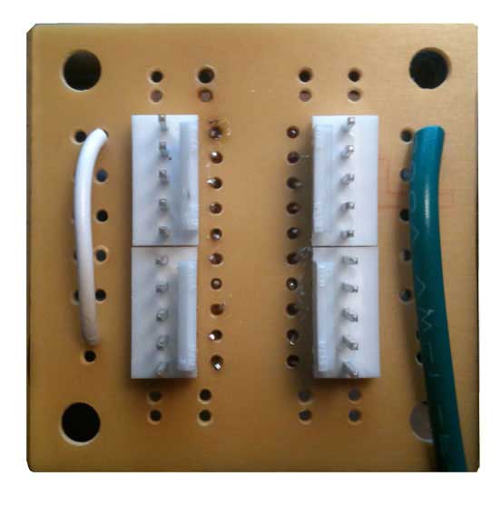
The assembled backplane connector. The wiring arrangement on the other side and is not seen here. The "A" terminal is at the top of the two connectors on the left and at the bottom of the two connectors on the right. (The MOLEX data sheet specifies that terminal as "CIRCUIT 1".) This reversed orientation of the connectors is critical to make the wiring very simple. There are two sets of connectors, paired horizontally. The green and white wires connects to power negative from the GND pins.
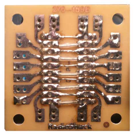
The assembled backplane connector, on the wiring side. The wiring is very simple: straight across for the two sets of paired connectors. This board looks a little rough because I had built another version of the backplane on it, and I had to remove that version, clean up the solder paths and holes, and then re-use the board for the new version. I'll try to get a new board and take better pictures. Also, these boards are not tinned, and the don't have plated-through holes. They can be tedious to solder.
The RADIO SHACK circuit board is no longer available. A replacement circuit board (and perhaps a better-suited product) is available from JAMECO ELECTRONICS. Their model SB300 solderable PC board costs $5 and should be useful for constructing the backplane connector board. One board could make several NMEA-0183 interconnecting backplane boards. I have also updated the prices for the Molex connectors to their 2023 costs.
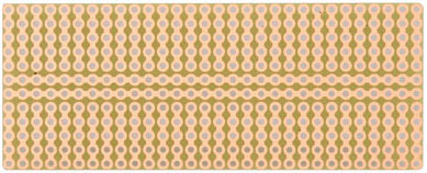
To replace the RADIO SHACK circuit board, the JAMECO ELECTRONICS SB300 is a good substitute.
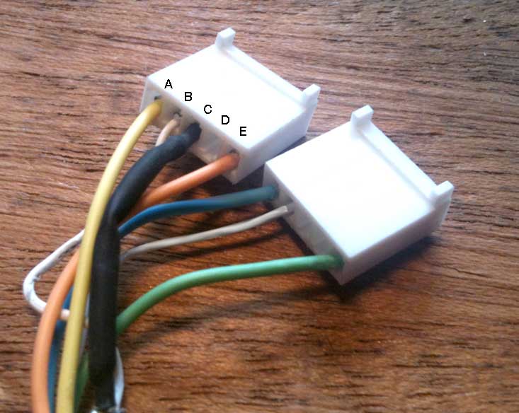
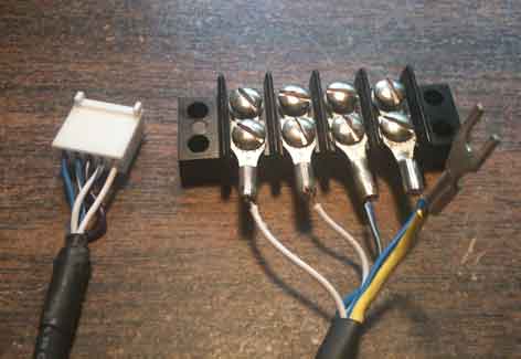
Wiring from HDS to connector for two ports with single-ended signals. Callouts identify the connector pins according to my labeling in this article.
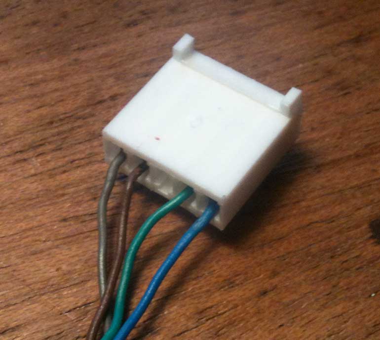
Wiring from GX1500S to connector for one port with differential signals.
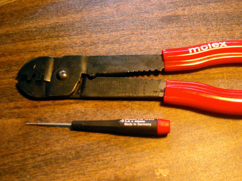
The MOLEX crimp tool and a very small 1.5-mm screwdriver used to manage the release of the terminals from the housing.
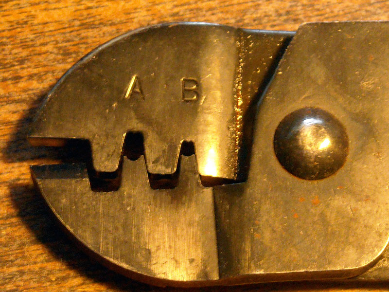
Detail of the crimp jaws.
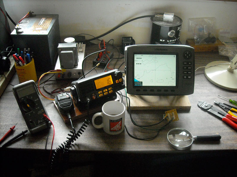
The work bench. The universal NMEA-0183 connection is in the foreground in front of the HDS-8.
The universal wiring approach to interconnecting NMEA-0183 devices does not require a specific connector or wiring device arrangement. One can use any sort of wiring device they like for the interconnection. The header with pins and push-on housing connector I show above are attractive due to their very low cost and wide availability.
It is also possible to reduce the interconnection to just four poles and omit the C-pole. However, I found the five-pole interconnection to be very useful. The first device I used to interface----the HDS--had five wires in its data cable because it can work as both a differential or a single ended source. The five-pole connector provides a place for the fifth wire to go. Another device I looked at early in this analysis did not provide any ground or shield wires. The use of the five-pole connector allows one to easily provide a ground for the transmit circuit to be referenced to, without having to create a new conductor in the data cable for the circuit, by use of the jumper between pins B and C. Otherwise one has to pick up the power negative, which may be in another cable, and run a new conductor over to the interface wiring. These two instances are why I used a five-pole connector. The extra pole is not absolutely needed, but it works out to be useful in several circumstances. The added cost of a five-pole versus a four-pole connector is inconsequential. I don't see any problem with a five pole connector because it makes the wiring handier. A four-pole connector could be used, but one would have to be diligent to always provide a ground or shield where needed, and the external ground on the backplane to pole E could not be used.
Soon after developing this universal interface method, I had need to connect some marine electronic devices to an RS-232 serial port interface on a DB-9M connector. I built a small adaptor by wiring a DB-9F connector to a 5-pin header connector. A RS-232 interface device is a 1/1 or singled-ended transmitter and single-ended receiver. The details of the adaptor are:
| NEMA to RS-232 Serial Port | ||||
|---|---|---|---|---|
| POLE | SIGNAL | WIRE COLOR | DB-9F PIN | RS232 SIGNAL |
| A | TALKER A | BLACK | 3 | TxData |
| B | TALKER B | WHITE | 5 | GND |
| C | GND | WHITE | 5 | GND |
| D | LISTENER B | None | - | No Connection |
| E | LISTENER A | RED | 2 | RxData |
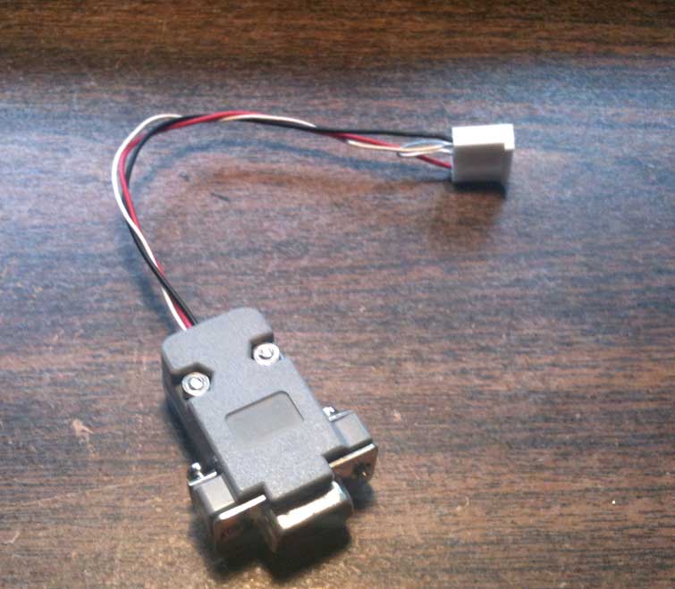
An adapter cable for RS-232 on DB9 to my Universal NMEA-0183 interface was fabricated.
When I began this project I was really just looking for a method of interconnecting devices that would use a suitable connector, that is, a small connector that was easily available and not very expensive. The MOLEX pin header and mating terminal easily satisfied those requirements. The next step was to design how the various device signals would be wired to the connector. It was then that the question of a consistent wiring method came under consideration.
After some investigation I realized that it would be possible to accommodate all ten variations of interfacing with a single method. The beauty of this approach did not reveal itself to me until I had actually made and connected a number of devices. At some point I wanted to add a new device to the system. In the past a detailed study of how to interconnect the new device to existing devices would have been necessary, but now, with the universal method, I only had to configure a connection of the device to the universal interface. Once properly terminated to the universal interface the rest of the proces would be automatic. This is the real beauty of using this method.
The National Marine Electronics Association (NMEA) has considered the problem of inconsistent use of wire color codes on the NMEA-0183 interface. There is a draft of a new standard proposed. If the new standard is adopted, and if manufacturers begin to conform to it, the interfacing of any two compliant devices would become much more consistent. A separate article discusses the new color code standard for NMEA-0183. To interface a NMEA-0183 device that followed the proposed standard for wire color using the my Universal method, the wiring would be as follows:
| NMEA 0183 Proposed Standard | ||
|---|---|---|
| POLE | SIGNAL | WIRE COLOR |
| A | TALKER A | WHITE |
| B | TALKER B | BROWN |
| C | GND | BLACK |
| D | LISTENER B | GREEN |
| E | LISTENER A | YELLOW |
My Universal NMEA-0183 wiring can be applied to many other connectors. Perhaps the simplest is a terminal strip. Consider a five-pole terminal strip with two terminals. Connect one device to the left side using the the five poles as A-B-C-D-E from top to bottom, and connect the second device using the five poles as A-B-C-D-E from bottom to top. This is shown below:
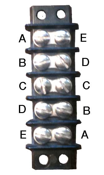
A commom five-pole terminal strip can also be used as a connection point for the Universal NMEA-0183 interface. Consider the terminals to identified as shown, and connect the two devices accordingly, one to each side.
I found I was working with many different radios in some testing I was doing. The radios all had their NMEA signals on wire fan outs. To connect them temporarily to my Universal Interface system, I made a little test adaptor. On one end I have my five terminal header connector, and on the other end a four-position terminal strip. I can connect the wire fan out from a radio under test to the terminal strip, and then connect the device to my Universal Interface. The adaptor is shown below.
A four-pole terminal strip is wired to a five-pole header connector.
The terminal strip connections can be considered as poles A-B-D-E, and the
unconnected shield or ground as pole C. For unbalanced signals "C" can be
connected as a jumper to B if needed. For balanced signals the shield is
not needed and is not connected. I use this interface to temporarily wire to
devices under test on my bench,
If this article has raised any questions or if you have a comment, feel free to post it to a discussion thread reserved for that purpose.
Copyright © 2011 by James W. Hebert. Unauthorized reproduction prohibited.
This is a verified HTML 4.01 document served to you from continuousWave
Author: James W. Hebert
This article first appeared December 21, 2011.
