A simple method and guide for interconnecting marine electronics using NMEA-083 is presented. A second article demonstrates an artful implementation of the method.
Installation of marine electronic devices often requires interconnection of the devices using a serial data link that conforms to the NMEA-0183 standard. While the NMEA-0183 standard has done a great job of creating an extremely useful and very compatible method of exchanging serial data between devices, the actual interconnection is often left to the boat owner. Most boat owners are not expert in serial data connections. To add to the difficulty, many manufacturers have only loosely complied with the recommended practices regarding identification of signals by name and color coding. This has led to confusion among installers. This guide is an effort to apply a few simple rules in order to make the interconnection process simpler and more easily accomplished by the average boater.
There are several elements of the interconnection, and all must be properly accomplished to have success:
Manufacturers tend to give descriptions or designations or nomenclature to the signals in an NMEA-0183 device that are not consistent with the recommendations. These names must be translated to the standard names or nomenclature. A guide for translation might be:
| Signal name translation | |
|---|---|
| Manufacturer | NMEA |
| Input, In, Receive, Rx, RX | LISTENER |
| Output, Out, Transmit, Tx, TX | TALKER |
Manufacturers have also tended to apply notations of plus-signs(+) or minus-signs (-) to their signals. This also must be translated to the standard names. A guide for translation might be:
| Signal name translation | |
|---|---|
| Manufacturer | NMEA |
| (+) | A |
| (-) | B |
Using these two guides, all the signal definitions from a manufacturer can be conformed to the standard NMEA nomenclature. In order to get the proper information, refer to the manufacturer's own literature for the signal definitions and colors. In some instances, this information can be buried in the literature, perhaps only shown in an illustration. Sometimes the information is shown only in separate installation manuals. Depend on the manufacturer's own literature, not on third party sources.
To demonstrate the signal name conforming process, let us consider the signals from a popular radio device, the Standard-Horizon GX1500S. Here are the original signals and their color codes as shown on page 11 of the owner's manual, and the translation to NMEA standard names:
| Signals GX1500S | ||
|---|---|---|
| Color | Manufacturer's Name | NMEA Name |
| BLUE | NMEA Input (+) | LISTENER A |
| GREEN | NMEA Input (-) | LISTENER B |
| GRAY | NMEA Output (+) | TALKER A |
| BROWN | NMEA Output (-) | TALKER B |
Once we have properly translated the signal names, we can forget about their original names. The signals from the GX1500S now look like this:
| NMEA Signals GX1500S | |
|---|---|
| Color | NMEA Name |
| BLUE | LISTENER A |
| GREEN | LISTENER B |
| GRAY | TALKER A |
| BROWN | TALKER B |
To demonstrate a connection, we need a second device. Let's use a Lowrance HDS-8. The signals from its NMEA-0183 will be found on pages 24 and 25 of the installation guide; they do not appear in the operating guide. The HDS-8 is somewhat unusual in that it can be configured to have one NMEA-0183 port or interface using the preferred differential signals (noted by Lowrance as RS-422) or to have two NMEA-0183 ports or interfaces using the non-preferred single-ended signals (noted by Lowrance as RS-232). For this example we will use the configuration for differential signals. The original signal names and the translation are:
| Signals HDS-8 Differential Mode | ||
|---|---|---|
| Color | Manufacturer's Name | NMEA Name |
| YELLOW | TX (+) | TALKER A |
| BLUE | TX (-) | TALKER B |
| ORANGE | RX (+) | LISTENER A |
| GREEN | RX (-) | LISTENER B |
Once we have properly translated the signal names, we again forget about their original names. The signals from the HDS-8 now look like this:
| NMEA SIGNALS HDS-8 RS-422 | |
|---|---|
| Color | NMEA Name |
| YELLOW | TALKER A |
| BLUE | TALKER B |
| ORANGE | LISTENER A |
| GREEN | LISTENER B |
To interconnect the two devices (e.g., GX1500S to HDS-8) we connect their signals together following a very simple rule:
LISTENER connects to the TALKER of the other device with the same A/B notation.
For example, LISTENER A of one device connects to TALKER A of the second device. Using our example devices, the wiring would be as follows:
| NMEA 0183 Connection between GX1500S and HDS-8 | ||||
|---|---|---|---|---|
| GX1500S | HDS-8 | |||
| Color | NMEA Name | Connection | NMEA Name | Color |
| BLUE | LISTENER A | <----- | TALKER A | YELLOW |
| GREEN | LISTENER B | <----- | TALKER B | BLUE |
| GRAY | TALKER A | -----> | LISTENER A | ORANGE |
| BROWN | TALKER B | -----> | LISTENER B | GREEN |
Figuring out interconnections when both devices are the recommended differential signal case is very straightforward. Unfortunately, devices are not always provided with differential signals. Devices with only single-ended interfaces won't have any of the "B" signals. The rules for interconnecting need to be modified to handle these alternative possibilities. The new rule is just a bit more complex. To interconnect the two devices we connect their signals together following this three-part rule:
LISTENER connects to the TALKER of the other device with the same A/B notation.
If a LISTENER B has no corresponding TALKER B signal, that LISTENER B connects to ground or the power source common (i.e., negative battery bus in most boats).
If a TALKER B has no corresponding LISTENER B, that TALKER B is insulated and left unconnected.
To give an example of the application of the new rule, we can use the HDS-8 in its single-ended mode (called RS-232 by Lowrance). We need to get the original signals and translate them. Because there are two ports, we identify them as Lowrance does, using the notation Com 1 and Com 2. Again, from the Lowrance installation guide page 25 we have:
| NMEA SIGNALS HDS-8 RS-232 | ||
|---|---|---|
| Color | Name | NMEA Name |
| YELLOW | Com 1 TX | TALKER A (for Com 1 |
| BLUE | Com 2 TX | TALKER A (or Com 2) |
| ORANGE | Com 1 RX | LISTENER A (for Com 1) |
| GREEN | Com 2 RX | LISTENER A (for Com 2) |
Because we are using only one port, Com 1, we simplify this and discard the original names:
| NMEA SIGNALS HDS-8 Single-ended Mode | |
|---|---|
| Color | NMEA Name |
| YELLOW | TALKER A |
| ORANGE | LISTENER A |
Now we interconnect with the HDS-8 using the three-part rule:
| GX1500S and HDS-8 single-ended mode | ||||
|---|---|---|---|---|
| GX1500S | HDS-8 | |||
| Color | NMEA Name | Connection | NMEA Name | Color |
| BLUE | LISTENER A | <----- | TALKER A | YELLOW |
| GREEN | LISTENER B | (to ground) | ||
| GRAY | TALKER A | -----> | LISTENER A | ORANGE |
| BROWN | TALKER B | (floats) | ||
As shown above, LISTENER A and TALKER A always connect. If you have a LISTENER B and there is no corresponding TALKER B, then LISTENER B goes to ground or power supply common. If you have a TALKER B and there is no corresponding LISTENER B, then TALKER B is left unconnected and insulated.
To review, there are simple steps to making NMEA-0183 connections. These are:
In many implementations of the NMEA-1083 interface on a marine electronic device, the physical layer provides the signals on individual wires in a cable, often called a wiring fan out. In this type of wiring, NMEA-0183 signals and their respective wires are identified only by the color of the wire insulation. It is very unfortunate that NMEA-0183 has not included a specific recommendation for wire colors for specific signals. Manufacturers have been implementing their own wire color, often in very confusing and inconsistent manners. The lack of standarization of wire colors adds a great deal of confusion to making interconnection of NMEA-0183 devices. Even harder to understand, manufacturers recently have shown inconsistent use of wire colors even among their own products of the same model designation, and have had to resort to providing errata sheets to owners of their products to correct errors in the documentation of their products. This is a horrible situation. There is no standard for wire colors, and very little consistency in even using them.
It is believed that NMEA is planning a revision to their NMEA-1083 standard. It is believed that at the present there is a proposal for a consistent color standard for NMEA-0183 wiring that follows this design:
| NMEA-0183 v4.0 Color Code | ||
|---|---|---|
| Name | Color | Descripton |
| TALKER A | White | Data-H |
| TALKER B | Brown | Data-L |
| LISTENER A | Yellow | Data-H |
| LISTENER B A | Green | Data-L |
| SHIELD | Bare | |
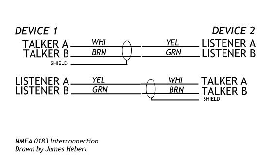
If two NMEA-0183 devices follow this recommendation for differential ports and color code of the wires, their interconnection would be as shown below. Note that the shield of the TALKER pair is only connected at the TALKER end of the cable. If a cable must be extended, the color code of the TALKER should be maintained in the extension:
There are some other non-wiring parameters to be considered when making serial data connections. Some additional details of the serial data exchange have to be considered. Also, the actual data being sent by a TALKER has to be of interest to the LISTENER. Most NMEA-0183 devices provide means to adjust these parameters
The NMEA-0183 interface typically requires the following parameters to be configured for the serial data port:
| NMEA-0183 Serial Port | |
|---|---|
| Parameter | Normal Configuration |
| Baud Rate | 4800 |
| Parity | None |
| Stop Bits | 1 |
| Handshake | None |
There is an alternative baud rate of 38400, which is typically used only for AIS devices, and is often referred to as NMEA-0183 HS (for High Speed). Some devices do not offer configuration of their NMEA-0183 ports. For those devices, you must connect a corresponding device that is properly configured. In most cases on NMEA-0183 devices, only the baud rate parameter is available for configuration. The other parameters are assumed to be fixed and set to the appropriate configuration. Interconnection with non-NMEA-0183 devices, like a serial port on a computer, will typically require more detailed configuration to set the serial port to the usual NMEA-0183 parameters.
Devices which have NMEA-0183 data to send usually permit configuration of the particular NMEA-0183 sentence that will be sent on a particular port. Each device typically provides a method to configure the data that it will send on its NMEA-0183 TALKER circuit. If a device has more than one NMEA-0183 TALKER circuit, it will be typically be able to be configured to sent different NMEA-0183 sentences on each TALKER. The data that should be sent is selected based on what the other device can understand and use. For example, it makes no sense to send NMEA-0183 data about depth to a DSC radio that does not understand that sentence. To determine what data to select for sending, consult the instructions for the device that will be the LISTENER. Each LISTENER device should give explicit instructions about the NMEA-0183 sentence it wants to receive.
DISCLAIMER: This information is believed to be accurate but there is no guarantee. We do our best!
Copyright © 2013 by James W. Hebert. Unauthorized reproduction prohibited!
This is a verified HTML 4.0 document served to you from continuousWave
URI: http://continuouswave.com
Last modified:
Author: James W. Hebert
This article first appeared February 26, 2013.
